When a design seems like it might not meet minimum steel, all hope is not lost
While there is no way around satisfying the minimum steel requirements in the CSA S304, there is a clause that can be taken advantage of that is not used by MASS. By following the procedure outlined in this article, beams can be designed within the restraints of the CSA standards while also containing less than the minimum reinforcement area as prescribed by clause 11.2.3.1. This often overlooked clause can be very helpful when it comes to masonry beam design, especially those that would seem at face value to be the easiest to design due to nominal loads and short spans.
July 2020 Update: This clause has been incorporated into the release of MASS Version 4.0.
Disclaimer: This post is exclusively intended to provide insight into the approach taken by the MASS design software in interpreting a CSA S304-14 code compliant design. It is up to the professional discretion of the designer to input an appropriate layout, boundary and loading conditions, interpret the results, and determine how they should be incorporated into their designs. As per the end user license agreement (and also recommended within PEO’s guidelines for using engineering software), a tool cannot be considered competent and reliance on a tool does not relieve the user of responsibility.
To jump straight to a summary further down the post, click here.
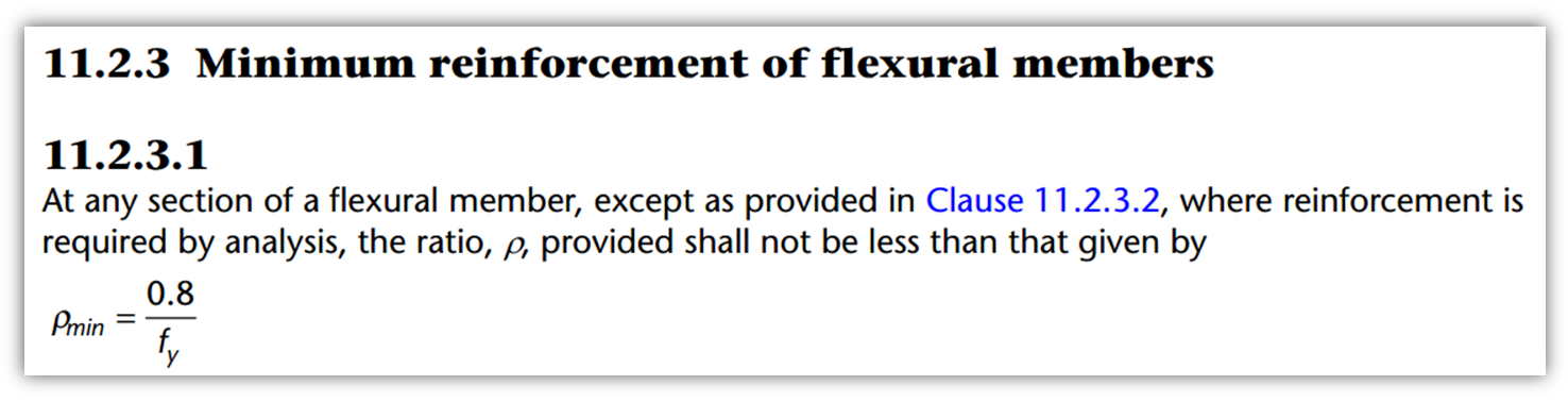
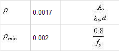
The smallest beams with only nominal loading can also be the trickiest to design. One of the reasons is the need to satisfy minimum reinforcement ratio requirements in S304-14: 11.2.3:
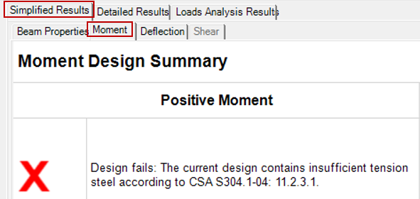
Currently in the MASS software, all beam designs not meeting ρmin in clause 11.2.3.1 will fail moment and deflection design, shown below in the simplified moment results tab:
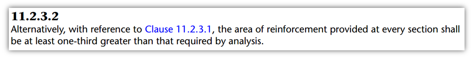
While these designs are failed before attempting an incrementally larger design with more reinforcement, there is an option at the engineer’s disposal outside of MASS: invoke the mighty power of clause 11.2.3.2 which often goes overlooked.
There was some initial due diligence behind including this clause in the MASS software. It was not included as programming costs would be very high. The change would involve functionally designing two beams; the first being the actual beam used for the design, and the second beam being the theoretical beam containing one third less reinforcement which would be used to resist the factored moment. While at first glance, it might seem acceptable to instead ensure that the beam has additional moment resistance by factor of 4/3. However, while it is very close, there is not quite a directly proportional relationship between a beam’s moment resistance and its longitudinal reinforcement area so this approach would not adequately reflect the phrasing of clause 11.2.3.2.
How to use this clause
There are two different approaches that can be taken to satisfy clause 11.2.3 and design a beam that contains less than the required reinforcement ratio, or ρmin, of clause 11.2.3.1:
Method 1
Compare the area of reinforcement to the area required by analysis increased by one third
Method 2
Compare the factored load to the load resisted by the beam if the reinforcement area were reduced by a third
Unfortunately, there is no way around completing a separate analysis to determine “the area of reinforcement required by analysis” quoted directly from the standard. Since the minimum reinforcement is a function of loading, one cannot be solved without assuming the other. Method 1 is likely more intuitive as it returns an alternative minimum reinforcement area to clause 11.2.3.1. However, Method 2 can be more straight forward to calculate as there is no need solve a quadratic or cubic function.
Method 1: Comparing areas of reinforcement
The approach taken in method 1 is to answer the question: “How much reinforcement is required in this beam design?”. This can be expanded to “What area of steel results in factored moment being equal to moment resistance?”. For beams with compression steel or intermediate steel which may not necessarily be yielding, it is likely easiest to solve for this value using a spreadsheet and GoalSeek or Solver since a simplified expression would likely require finding the roots of a cubic function and would also rely upon an assumed strain profile if the steel is yielding. Minimum reinforcement failure messages do not tend to present themselves for beams with several layers of steel so this article will focus on the simple beam designs where these issues arise.
The area of steel required, or Asreq, can be solved for using force and moment equilibrium for any beam configuration where the beam’s moment resistance is equal to the maximum factored moment (Mr = Mf). The expression below can be used calculate this minimum area of reinforcement for beams with only tension reinforcement:
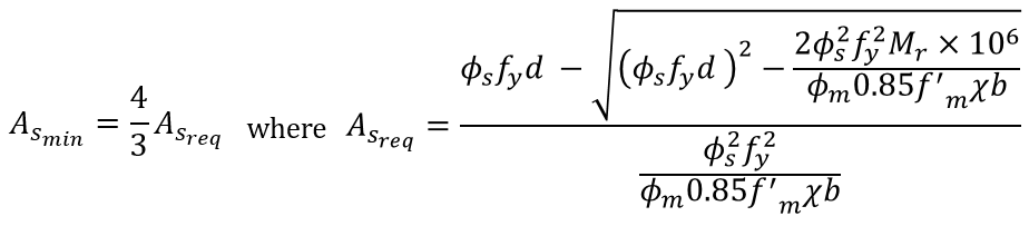
Note that this expression is only applicable to beams that exclusively contain primary tension steel to resist flexure (ie. no intermediate or compression steel). This formula also assumes that the tension steel is yielding which is a requirement in clause 11.2.2. Also, while the area of reinforcement required is typically a function of a beam’s moment resistance, it is possible that other factors such as cracking and deflection may govern the design and as such, should never be assumed to be satisfied and always checked manually (in addition to using this formula).
The units of each input are shown below as well as the derivation which can be expanded.
Units - click to expand
Asmin, Asreq are both areas in mm2
Φs, Φm, χ are unitless
fs, f’m are strengths in MPa (or N/mm2)
d, b are both lengths in mm
Mr is the moment resistance (set equal to factored moment) in kN*m
Note: Mr is multiplied by 106 to convert the value from kN*m to N*mm
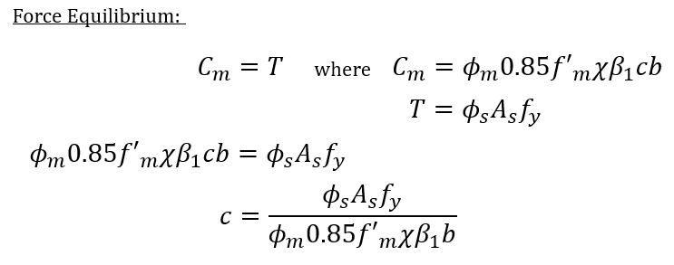
Expression derivation - click to expand
Starting with force equilibrium of a simple beam in bending, an expression for c can be rearranged based on all other inputs.
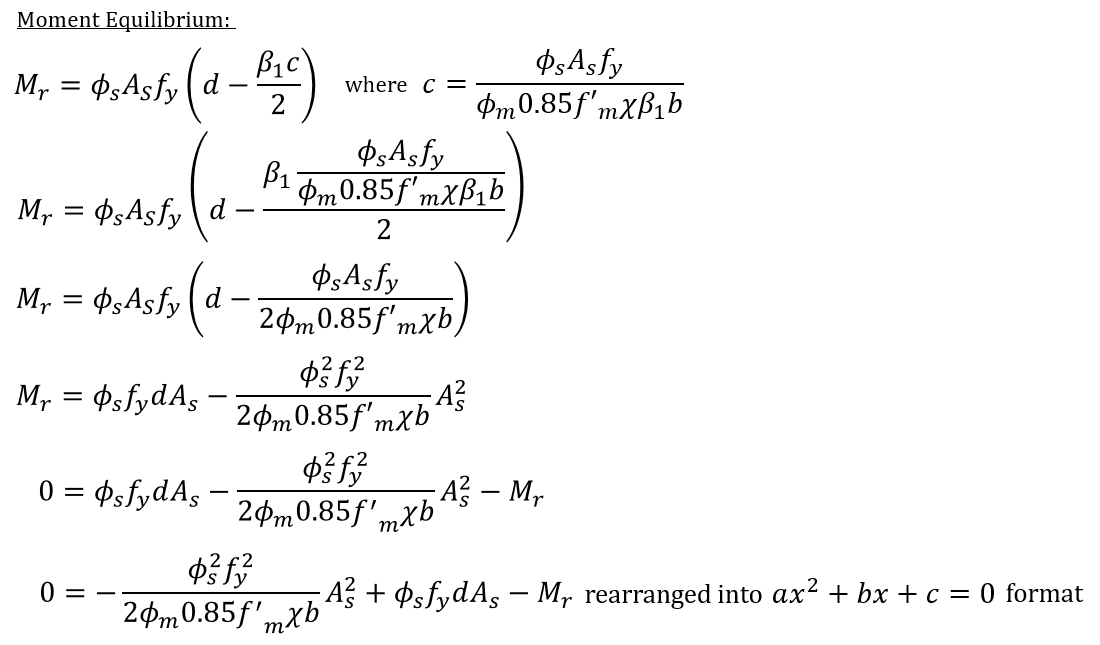
This expression can be substituted into a moment equilibrium equation which can be rearranged into ax2 + bx + c = 0 format.
Now, recall (from grade 10 math) how to solve for the roots of a quadratic. In this case, it is the positive root which gives the simplified expression for Asreq that we can use (The other root is not a valid solution since it is orders of magnitudes larger, violating strain profile assumptions which are used to generate the expression).
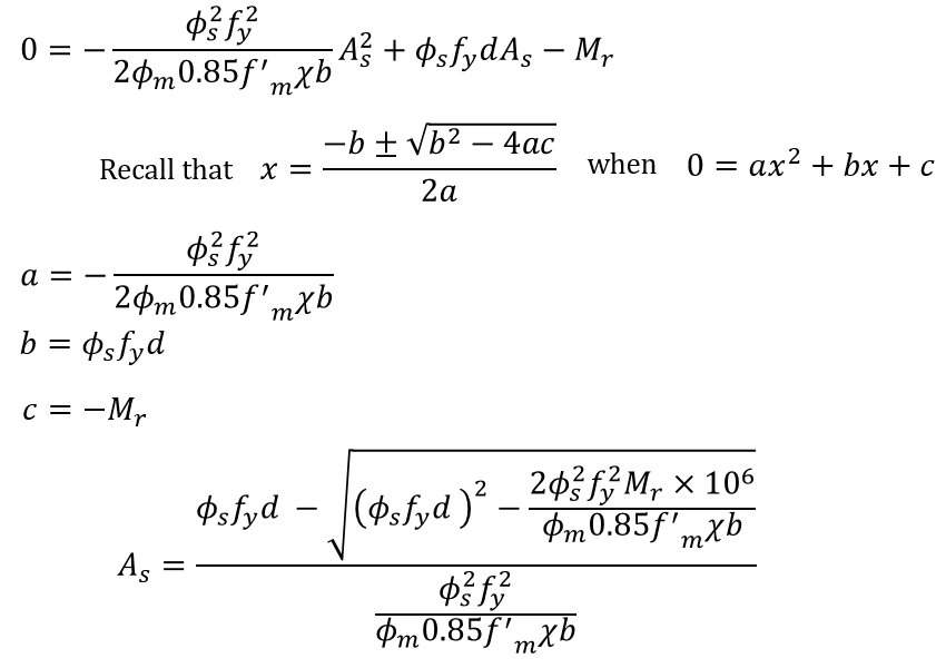
Quick note regarding the other root: The positive root in the original quadratic solution end up with the expression above with a negative sign in front of the square root term once substitutions have been made and then simplified. Had the expression been arranged on the left side of the equal sign rather than the right (as was done above) then we would be using the negative root, with a positive sign in front of the square root term with all other terms having flipped to negative.
The simplified expression no longer contains the plus/minus symbol to omit the other root that is not relevant in checking minimum steel. This is because it results in a required area of steel which is order of magnitudes larger than the value we are interested and the internal cross section forces as well as the strain profile used to derive this expression are no longer valid when the area of steel is so large. For example, in the scenario in the collapsible section below, a 2 course beam requires either an area of steel at the balanced condition of 8.64mm2 or 105,633mm2. If we were to entertain the second solution as possibly being valid, this would result in a tension force coupling with almost 36,000,000kN from the masonry. This would require a beam with a compression depth of more than 70m so hopefully by now it is clear how far outside the scope of our original beam we have wandered. With that new ridiculous new neutral axis location, the steel is no longer in the tension side of the beam which is one of the areas where things fall apart. From a pure mathematical perspective, it does satisfy the equation but the conditions behind that expression are no longer valid at such large values of As,req.
Method 1 Example (with MASS input)
Consider 1.2m long opening within a concrete block elevation that is being spanned by a masonry beam which rests upon 200mm supports on either side. Note that the bearing length has been shortened from the default 300mm further explained here.
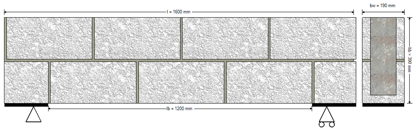
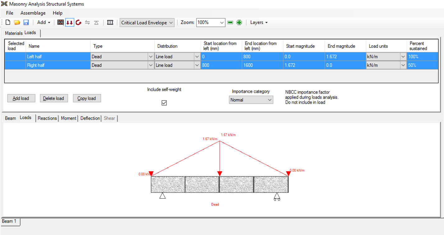
Assuming that the condition for arching are present (see Section 5.6. Load Distribution on lintel Beams in our textbook for more), the loading can be modeled as two triangularly distributed loads plus the self-weight of the beam itself. In this case, the maximum magnitude of the masonry supported by arching (assuming hollow masonry in the three courses above the grouted beam) is 1.672 kN/m, or 800mm (length of beam divided by 2) multiplied by 2.19kN/m2 (the weight per square metre of wall which can be found on page 751, here, for all unit sizes and types)
If using a 20cm, 15MPa unit, this beam will initially fail moment design, citing the following failure message:
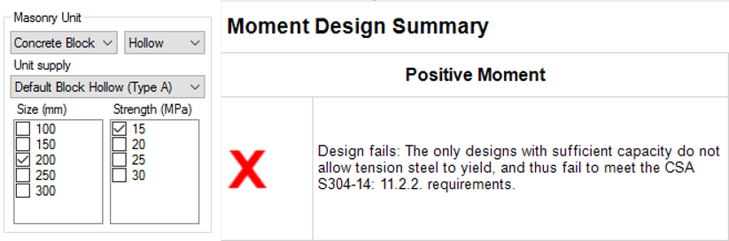
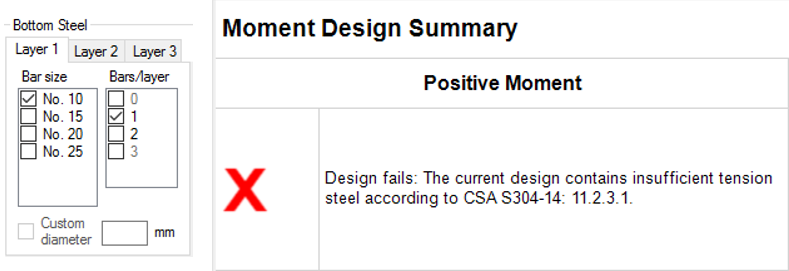
Keep in mind that when a design in MASS fails, the displayed error corresponds to the most recently attempted design. In this case, the error message is based on a beam with several No. 25 longitudinal bars placed in tension. Earlier sections that would have been attempted could have failed for a number of reasons and in this case where the loading is nominal, sections not containing the minimum steel ratio in clause 11.2.3.1 result in the error message displayed at the top of this post. It can be triggered in MASS by deselecting all reinforcement options other than one No. 10 bar placed at the bottom of the beam.
The actual reinforcement ratio of this “failing design” can be found by clicking on the Detailed Moment Results tab and scrolling down to the bottom:
While it fails according to MASS, designs such as these are prime candidates for invoking the mighty power of clause 11.2.3.2.
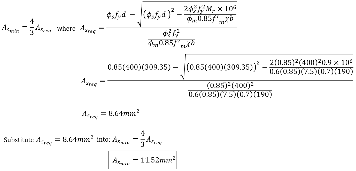
This beam with a single No. 10 bar (100mm2) has more than eleven times the area of reinforcement required by analysis (8.64mm2) and easily exceeds requirement of having an additional one-third. Compared to the limit from clause 11.2.3.1, which would require 117.6mm2 (0.002ρ = 0.002*190mm*309.35mm), this is the S304’s way of taking light loading into account for these types of designs.
To further illustrate this relationship, As,min plotted as a function of Mf is shown below:
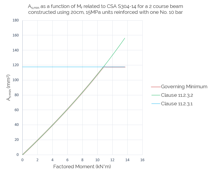
Since the area of a No. 10 bar is less than the area required by 11.2.3.1, it is necessary to use clause 11.2.3.2 to satisfy minimum steel. The relationship between Asmin and Mf is very close to linear (R2 = 0.997) so for each 1kN*m increase in factored moment, roughly 11.3mm2 of steel is required (Note that this relationship is specific to a particular beam configuration and cannot be applied to others).
Method 2: Comparing Loads
Rather than ask the question, “What is the minimum area of reinforcement needed?” for a beam design, the other way to approach satisfying clause 11.2.3.2 is to assume that the area of steel present is equal to the minimum allowable and determine the largest possible factored moment that the assumption is valid for. Since this clause takes loading into account to evaluate minimum steel, rather than use a load to check the area of steel, method 2 involves using an area of steel to check the load. As mentioned earlier, this method may appear less intuitive as it is not as simple as comparing the reinforcement present to another minimum value. However, the steps used to determine the maximum allowable are the same as those used to calculate the moment resistance of any other beam design which is why method 2 may be preferable.
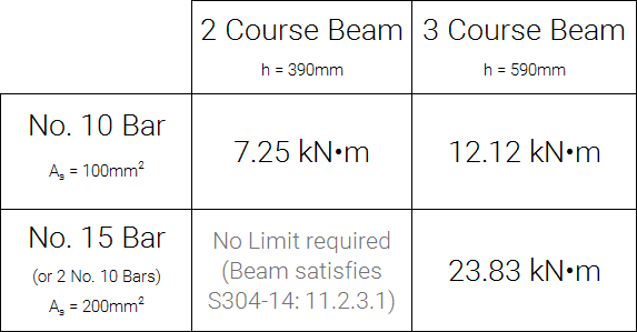
The table below shows a summary of the maximum allowable factored moments resisted by beams which contain less reinforcement than allowable by clause 11.2.3.1 for four possible beam geometries:
Maximum applied factored moment for a beams having less than the required reinforcement ratio in accordance with S304-14: 11.2.3.1 to satisfy S304-14: 11.2.3.2
Disclaimer: These values should not be relied upon as part of the design process. They are meant to illustrate the concept that very low areas of reinforcement may be acceptable, depending on the applied loads. The full cross section should be analyzed by the engineer by hand (or other tool) to check these requirements in a way that is applicable to the situation.
As stated under the simplified method 1 expression earlier, although the area of steel required is typically governed by moment resistance, it is possible that other factors such as cracking and deflection may govern the design and as such, should never be assumed to be satisfied and always checked manually.
Table assumptions and background information
This table is only meant to be a guide to assist the engineer in designing a beam that does not satisfy minimum steel requirements in MASS which only checks against clause 11.2.3.1. An example outlining the exact process can be found further below by clicking on the expandable heading: “Method 2 Example“.
Masonry unit properties such as length, height thickness, and face shell thickness were set to the default values used by MASS according to the default masonry unit database. These values can be found on p751 to p753 of our textbook. Reinforcement placement was also assumed to be the same as the default bar placement used in MASS for each unit and reinforcing bar size which is based on a 75mm vertical clearance from the bottom face of the beam to the closest face of the bar. A yield strain of 0.002 was used for all bars with an elastic modulus of 200,000 MPa.
Obviously there are other properties such as masonry unit size and strength which will also affect these values and can be found by expanding the detailed table below. The table was simplified relatively late in this investigation exercise after observing how little variance there was in maximum factored moment as a function of unit size and strength. Factored moment was selected as the limiting variable for this table so that it would be independent of a beam’s span or load magnitude (a large span would be limited to a considerably smaller uniformly distributed load compared to that of a smaller span).
Expanded table taking unit size and strength into account
Maximum applied factored moment for a beams having less than the required reinforcement ratio in accordance with S304-14: 11.2.3.1 to satisfy S304-14: 11.2.3.2
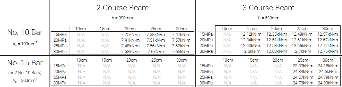
Disclaimer: These values should not be relied upon as part of the design process. They are meant to illustrate the concept that very low areas of reinforcement may be acceptable, depending on the applied loads. The full cross section should be analyzed by the engineer by hand (or other tool) to check these requirements in a way that is applicable to the situation.
Within each beam arrangement (ie. “2 Course Beam” with a “No. 15 Bar”), there is a smaller table where the column headings refer to masonry unit sizes (10cm, 15cm, 20cm, etc.) and the row headings refer to masonry unit strength (15MPa, 20MPa, etc.). As mentioned earlier, the variance within each beam arrangement was found to be relatively low.
All “N/A” values refer to configurations which satisfy clause 11.2.3.1 and will currently pass using MASS, independent of loading. Designs that did not result in strain profiles with yielding reinforcement were also checked against and removed as they are not allowable in accordance with S304-14: 11.2.2. There were not found to be any configurations that did not yield that also did not contain the reinforcement ratio required by clause 11.2.3.1. This was expected as yielding errors are a result of a beam containing too much reinforcement, increasing the coupled compression zone and lowering the location of the neutral axis while reducing the strain of reinforcement in tension.
Note that for designs using 2 No. 10 bars in tension (same bar area as 1 No. 15 bar), the placement is affected as the distance from the compression face of the beam is slightly further away from the vertical centroid of the bars. This change increases the moment arm separating the coupled internal forces and slightly increases the maximum allowable moment for these designs. The lower (and more conservative) values are shown in the table for simplicity however the comparison can be expanded below.
Maximum factored moment using 2 No. 10's compared to 1 No. 15 bar
Maximum factored moment for a 3 course beam with 1 No. 15 Bar (d = 507mm):
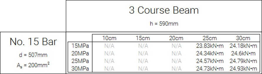
Disclaimer: These values should not be relied upon as part of the design process. They are meant to illustrate the concept that very low areas of reinforcement may be acceptable, depending on the applied loads. The full cross section should be analyzed by the engineer by hand (or other tool) to check these requirements in a way that is applicable to the situation.
Maximum factored moment for a 3 course beam with 2 No. 10 Bars (d = 509.35mm):
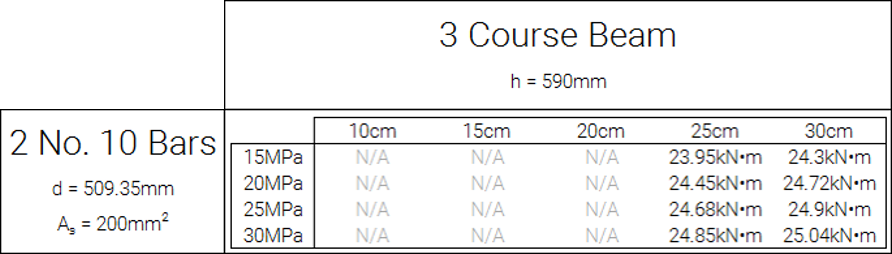
Disclaimer: These values should not be relied upon as part of the design process. They are meant to illustrate the concept that very low areas of reinforcement may be acceptable, depending on the applied loads. The full cross section should be analyzed by the engineer by hand (or other tool) to check these requirements in a way that is applicable to the situation.
Method 2 Example
Having already established that 7mm2 of longitudinal steel is sufficient in satisfying 11.2.3, what is the largest moment that can be applied to a beam containing one No. 10 bar?
Since the requirements of 11.2.3.2 are a function of loading where minimum reinforcement area increases with loading, the highest load can be found by assuming that exactly the minimum cross sectional area is present within the beam. If a No. 10 bar has an area of 100mm2 which is also equal to the minimum, the moment resistance will be based on a beam with 3/4 the steel, or 75mm2.
Note: 3/4 was used rather than 2/3 due to the interpretation of “at least one third greater” from clause 11.2.3.2 being represented as “1 + 1/3” or “4/3” of the area required. The inverse, or 3/4, can be used to use this clause to check the design with a known area of reinforcement.
Continuing with the beam in the earlier example (20cm, 15mPa unit reinforced using a No. 10 bar, loaded up to 0.9 kN*m), the location of the neutral axis can be determined, followed by the moment resistance:
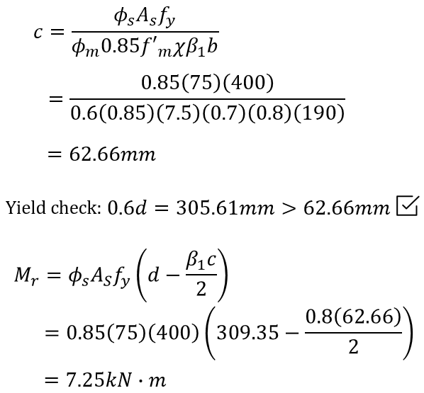
The moment resistance solved for here represents the maximum allowable load for the provisions of clause 11.2.3.2.to be valid. Therefore, the beam satisfies the CSA S304-14:11.2.3 minimum reinforcement requirements as long as the factored moment does not exceed 7.25kN*m (specific to the example beam constructed with 20cm, 15MPa units reinforced using a single No. 10 bar). Since the example beam was loaded to only 0.9kN*m, minimum steel requirements are satisfied.
The same procedure was followed for all of the other entries in the expanded table where unit size and strength are considered. For example, a 2 course beam constructed using 30cm, 25mPa units reinforced with a No. 15 bar can be loaded up to a bending moment or 24.79kN*m. (Note: The simplified table lists 23.83kN*m which is based the most conservative configuration which in this case is a 25cm, 15MPa unit)
Final Summary
All hope is not lost when a beam design fails due to not satisfying minimum steel using MASS, which only checks against CSA S304-14: 11.2.3.1. It is possible to satisfy minimum reinforcement requirements by instead using clause 11.2.3.2 by approaching the design in one of two ways:
- Method 1: checking bar area against one third greater than the area resulting in Mf being equal to Mr
- This can be done quickly for beams with only primary tension reinforcement using the following expression:
- Method 2: checking factored moment against moment resistance for a beam with a third less steel than what is actually present within the beam.
- This can be quickly checked by comparing the factored moment to the maximum allowable moment in the table below:
Disclaimer: These values should not be relied upon as part of the design process. They are meant to illustrate the concept that very low areas of reinforcement may be acceptable, depending on the applied loads. The full cross section should be analyzed by the engineer by hand (or other tool) to check these requirements in a way that is applicable to the situation. Regardless of which method is used, it is up to the designer to ensure that in addition to satisfying the minimum reinforcement requirements in S304-14:11.3.2, all other provisions must be considered and independently verified. The guides in both methods are based on the area of reinforcement being governed by applied bending moment at any section within the beam which is not true for all cases.
As always, feel free to contact us if you have any questions at all. CMDC is the authorized service provider for the MASS software which is a joint effort of between CCMPA and CMDC.