
Understanding the issue, when it can come up, and what can be done to account for it
When software bugs are found, notifications are posted in the MASS website Known Bugs page, on the MASS welcome screen, as well as here on the CMDC website software blog in an effort to be transparent and keep all MASS users informed. This issue was found within our own office as a result of an inquiry from a MASS user that resulted in this post. The bug was found some time after and as a result, the fix was incorporated into MASS Version 3.0, as well as a modified copy of Version 2.2 specifically to address this issue (click here to read more about Version 2.2.1).
This post outlines the conditions required to trigger this error, the designs where this could have affected design results, the details of the bug itself, and how to check to see if this bug is present in any MASS project.
Jump straight to:
- Bug Summary
- Background information
- What types of designs might be affected
- How to check if a design is affected
- Example
- Our Response
Bug Summary
Under a very specific combination of conditions, MASS may calculate the critical axial load for a reinforced wall, Pcr using both (EI)eff of 0.4EmI0 and Φer of 0.75, resulting in a Pcr value that incorrectly combines aspects of reinforced and unreinforced analysis.
This bug only affects designs where all of the following conditions are met:
- vertical reinforcement is not in tension
- load combinations with steel in compression also govern the design
- the wall experiences slenderness effects but is not a slender wall (kh/t > 30)
If MASS designs a wall where the vertical steel is in tension, all of the software’s results are correct. The same is true if any of the other conditions listed above is not true. The unlikely combination of circumstances is the reason why most wall designs are not affected and also why this bug has not been discovered until recently. This has been addressed in MASS Version 3.0 as well as in an updated Version 2.2.1.
Background information
If a wall is reinforced, why is it a problem to use the reinforced reduction factor when it comes to slenderness effects?
There is no problem as long as everything else in the calculations is also treating the wall as if it were reinforced. The issue comes from the way in which MASS sometimes treats the wall as if it were unreinforced when the steel is not in tension. This is done intentionally as ignoring the steel allows the software to use CSA S304 chapter 7 clauses governing the analysis of unreinforced walls when it is beneficial. This also assumes that the addition of steel to an unreinforced (but still grouted) wall will not reduce its capacity. For a full explanation on RM/URM analysis for reinforced walls, click here.
Differences between treating the wall as reinforced vs. unreinforced
Reinforced analysis compared to unreinforced differs in two ways when it comes to determining slenderness effects of a wall:
- Φe vs. Φer – Resistance factors for member stiffness used for slenderness effects
- (EI)eff – Effective stiffness for consideration of slenderness
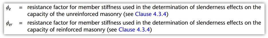
Resistance Factors – Φe vs. Φer
There are two different resistance factors that are used in calculating the critical axial compressive load used for determining slenderness effects; Φe for unreinforced walls, and Φer for reinforced walls. Click the heading below to expand the CSA references from which these resistance factors are based upon.
S304-14 clauses relating to Φe and Φer
From the Standard notation section of CSA S304-14: 2.2.2
And the clause referenced from 2.2.2:
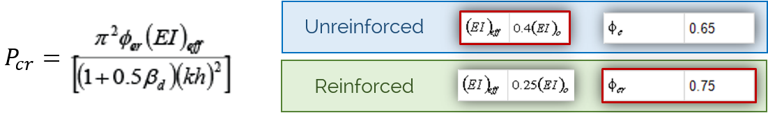
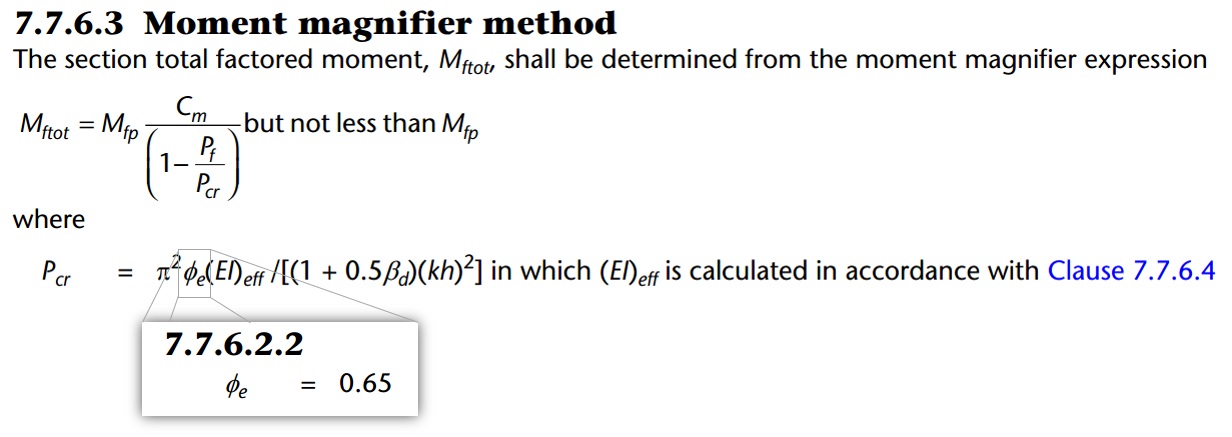
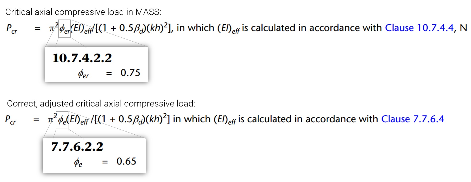
When determining the critical axial compressive load, Pcr, one of two similar formulas is used depending on whether the wall is reinforced or not. The formulas are identical with the exception of the resistance factor. For unreinforced masonry walls, the formula in Chapter 7 using Φe is applied:
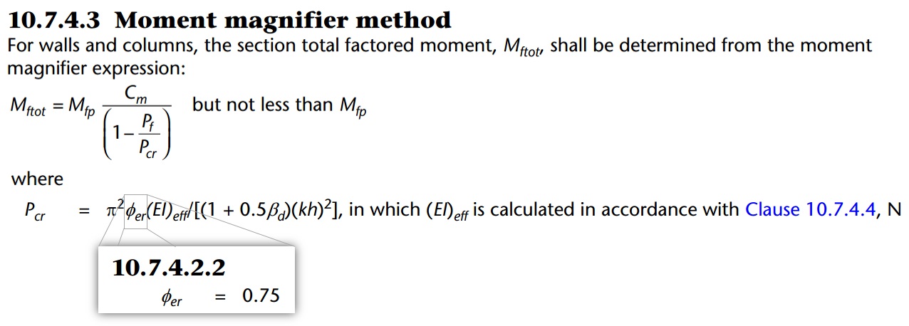
For reinforced masonry, the formula in Chapter 10 using Φer is applied:
As stated at the beginning of this post, the bug is that for reinforced walls, the reinforced reduction factor is sometimes incorrectly applied, using Φer rather than Φe. On its own, this would not be an issue, however, when combined with the reinforcement assumptions used in determining effective stiffness, there can be a “mixing” of assumptions that results in this bug.
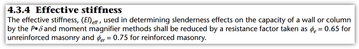
Effective stiffness – (EI)eff
Similar to the resistance factors, the formula used to determine effective stiffness for slenderness effects is a function of whether or not the wall is reinforced. Effective stiffness, or (EI)eff, for unreinforced walls is 0.4EmI0 while (EI)eff for reinforced walls is 0.25EmI0 (where the applied eccentricity is relatively low, below the Kern eccentricity). Click the heading below to expand the CSA references related to effective stiffness.
S304-14 clauses related to effective stiffness
(EI)eff for unreinforced walls is specified in clause 7.7.6.4:

(EI)eff for reinforced walls is specified in clause 10.7.4.4:
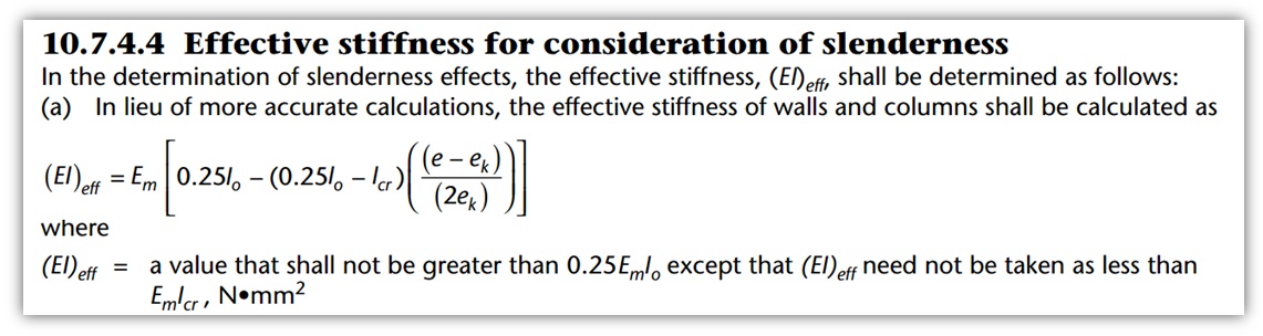
Due to the structure of the (EI)eff formula, all scenarios where the applied eccentricity (applied moment divided by the corresponding applied axial load) is below that of the Kern eccentricity, ek, will result in an effective stiffness of 0.25EmI0. Recall that ek represents the eccentricity at which the neutral axis under elastic bending and compression is at the outer edge of the cross section and is equal to the section modulus divided by the effective cross sectional area of the cross section (found in the list of terms further below in 10.7.4.4).
Reinforced walls with low eccentricities have an effective stiffness capped at 0.25EmI0. Compared to 0.4EmI0 which is used for unreinforced walls, there is a 37.5% reduction in stiffness simply for using the reinforced equation for the same wall design. Taking advantage of the unreinforced effective stiffness is what also mandates the use of Φe rather than the higher Φer.
What types of wall designs are affected?
As mentioned in the summary shown here,
- vertical reinforcement is not in tension
- c is greater than d for any bar
- load combinations where c exceeds d also govern the design
- Load combinations with higher axial loads are more likely to have the neutral axis exceed d while load combinations with both low axial load applied with high bending moment are typically closer to a wall’s interaction diagram envelope curve
- the wall experiences slenderness effects but is not a slender wall
- Slenderness ratio, kh/t, is greater than 10 – 3.5[e1/e2] specified in S304-14: 10.7.3.3.1 but less than 30 where axial load is governed by S304-14: 10.7.4.6.4
The only wall designs affected by this bug are those which have axial loads so high that the steel is no longer in tension AND experience slenderness effects without being classified as slender walls (S304-14: 10.7.4.6). Many wall designs that are governed by slenderness effects also require compression forces in masonry coupling with reinforcement in tension and are therefore not affected. For example, single spans with only self-weight and some nominal loads transferred from roof level are often not loaded with enough axial load to move the location of the neutral axis beyond the depth of steel in the wall.
Additionally, in order for a design to be impacted by the presence of this issue, the load combinations where the circumstances above are present must also be critical to the design. Load combinations with the highest axial loads (for example: 1.4D) are most likely to also be governed by load combinations using high lateral loads combined AND lower axial loads (for example: 0.9D + 1.4W).
It might even be easier to rule out the wall designs that are not affected:
- all slender walls are unaffected and correctly handled within MASS
- all walls using vertical reinforcement in tension (bars are ignored in compression as they cannot be adequately tied) are unaffected
- all walls that do not have any slenderness effects are not affected
Most wall designs fall into one (or more) of these three categories and it takes a special combination of circumstances to trigger a design that results in this bug affecting software result
How to tell if a design is affected
Check to see if the steel is in tension
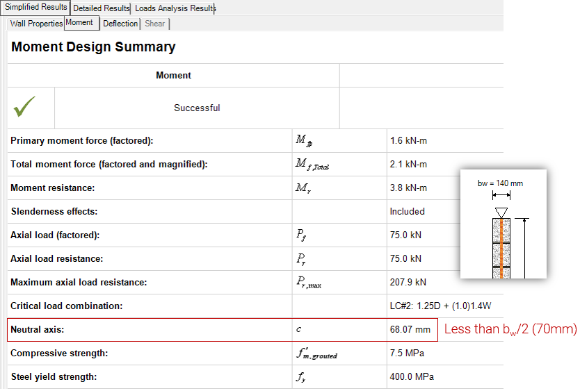
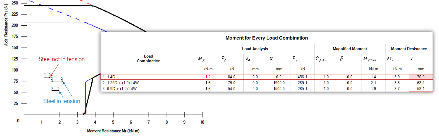
Look at the location of the neutral axis and compare it to where the vertical bars are placed. If the distance to the neutral axis, c, is less than the depth to the layer of reinforcement, d, then the steel is in tension and your design is not affected.
In this example, a wall constructed using 15cm units (thickness of 140mm) can be checked to see if the steel is in tension by comparing the Neutral axis value in the Simplified Moment Results window to the steel depth, d, which is placed in the middle of the wall (bw/2).
Steel is in tension (c<d)
Check to see if that load case governs the design result
As mentioned earlier, the load cases resulting in the steel not being in tension tend to differ from the load cases that govern the final design result (1.4D compared to 1.25D or 0.9D + 1.4W). When this is the case, the design is unaffected by the result. The example file highlights this aspect where the load combination resulting in steel being ignored (L.C. #1) is not critical to the design. In this case, load combinations 2 and 3 have total factored moments that are closer to the envelope curve which are based on the correct critical compressive axial load.
Out-of-plane wall designs tend to be governed by load combinations that combine the largest lateral load with the lowest axial load which are more likely to include steel in tension.
Note: To recreate this example for yourself, design a 3m tall, simply supported wall using 15cm, 15MPa units. Apply an unfactored axial dead load of 60kN, turn off self-weight, and apply an unfactored uniformly distributed wind load of 1 kN/m (or 1 kPa when considering a 1m length of wall as is the case for MASS wall modules). When designing for moment and deflection, at the first thing that will happen is that the wall will correctly pass being designed as unreinforced. For the purposes of highlighting this bug, de-select the 0 bars/cell option, effectively forcing reinforcement to be placed in the wall and skipping any iterations that are reinforced.
If the wall design is affected, compare the Mr to the manually adjusted value of Mf,tot
If the bug is present in a MASS project, the total factored moment resistance can be adjusted using the following expression:
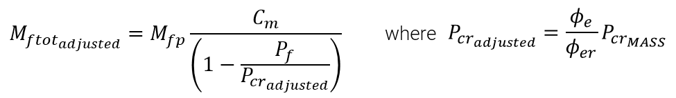
Mftotadjusted represents the adjusted value for the total factored moment taking slenderness effects into account
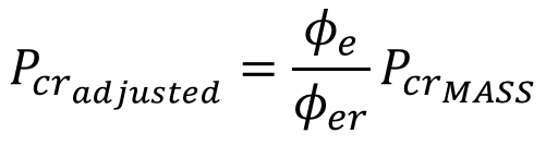
Pcradjusted represents the adjusted critical axial compressive load
PcrMASS is the critical axial compressive load calculated by MASS for load combinations where the bug is present in the results.
All other terms are defined within the CSA S304-14.
Both a derivation of the Pcradjusted expression as well as an example demonstrating how to use it can be expanded in the two sections below by clicking on each heading:
Background
The resistance factor is the only difference between the adjusted Pcr value and the value used in MASS. This can easily be corrected by multiplying the value in the software by a ratio of the correctly applied resistance factor, Φe, to the resistance factor used in MASS, Φer.
The critical axial compressive loads and their differences are shown in the figure below:
Example
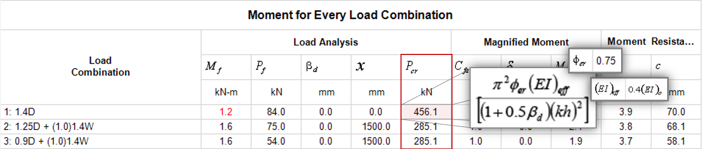
For the example scenario shown earlier, load combination #1 satisfies all of the criteria for this bug to be present. Pcr has been incorrectly calculated as 456.1 kN. Recall that to create this example, design a 3m tall, simply supported wall using 15cm, 15MPa units. Apply an unfactored axial dead load of 60 kN, turn off self-weight, and apply an unfactored uniformly distributed wind load of 1 kN/m. When designing for moment and deflection, at the first thing that will happen is that the wall will correctly pass being designed as unreinforced. For the purposes of highlighting this bug, de-select the 0 bars/cell option, effectively forcing reinforcement to be placed in the wall and skipping any iterations that are reinforced.
From looking at MASS outputs, the following information can be obtained to manually adjust Mftot:
- Pcr was determined by MASS to be 456.1 kN (PcrMASS)
- Primary factored moment before slenderness effects are taken into account, Mfp, is 1.2 kN*m
- Factored axial load, Pf, is 84.0 kN and moment diagram factor (see CSA S304-14: 7.7.6.5) is 1.0.
Adjusted critical axial compressive load can first be calculated and from that result, the adjusted total factored moment can be determined.
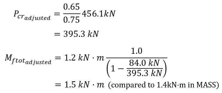
This value can be compared to the moment resistance (corresponding to the same axial load of 84.0 kN) to determine whether or not the design of the wall is still adequate for bending moment capacity. Mr can be found in the same table as the other slenderness data, which for load combination #1 is 3.9 kN*m which is still well beyond and corrected Mftot value.
This example highlights a case where the design is still adequate, even after manually checking the adjusted total factored moment.
It is expected that most designs will not meet all of the criteria for the bug to be present as the reinforcement is in tension for most reinforced wall designs. For those designs where the bug is present, it is possible for the the marginal difference in total factored moment to result in a failed design which would have been thought to have passed moment and deflection design. As mentioned earlier, the specific and unlikely combination of circumstances required to trigger this bug within MASS is the likely reason why it has remained undiscovered for so long.
Our Response
Bugs of this nature are taken very seriously. It was discovered in-house but not until very late in the Version 3.0 development process after it had been initially thought to be complete. As a result, the bug was investigated and a fix was added to Version 3.0 as well as to Version 2.2 in the form of MASS Version 2.2.1 (included in the installation directory for Version 3.0 – click here to read more). It has also been posted on our Known Bugs page where it links to this article.
If there is any question regarding the integrity of the results for a specific MASS project file, please feel free to contact CMDC directly. As the authorized MASS technical service provider, CMDC is available to help designers understand the specifics of identifying this issue, as well as any other masonry related technical questions. Click here for more information on technical assistance offered by CMDC.