Getting the most out of MASS is easy once you understand how to model your design within the software
The vast majority of masonry walls designed to resist out-of-plane bending are supported at the top and bottom, spanning vertically. Once you start looking at designs where a wall is spanning horizontally between columns, intersecting walls, or other supports, you are no longer within the scope of MASS. This does not mean that MASS cannot be a useful tool in designing a horizontally spanning wall! Continue reading to see how you can manipulate the software to assist you in your design.
For a quick checklist summary, click here to jump down the the end of this post.
Disclaimer: By using MASS to design horizontally spanning walls, it is up to you, the engineer, to ensure that all of the differences between vertical and horizontal spanning walls are properly accounted for within MASS. If there is any doubt of having a complete and comprehensive understanding of how to model these differences, it is best to perform these calculations by hand.
In order to design a horizontal span using the MASS wall module, it is important to understand the key differences between vertical and horizontal spans:
-
Geometry
-
Masonry strength in relation to the masonry bond pattern
-
Axial load
Before diving into these differences one by one, it is first valuable to review the base assumptions that area made within the MASS out-of-plane wall module. These cannot be changed and must be accounted for in other ways.
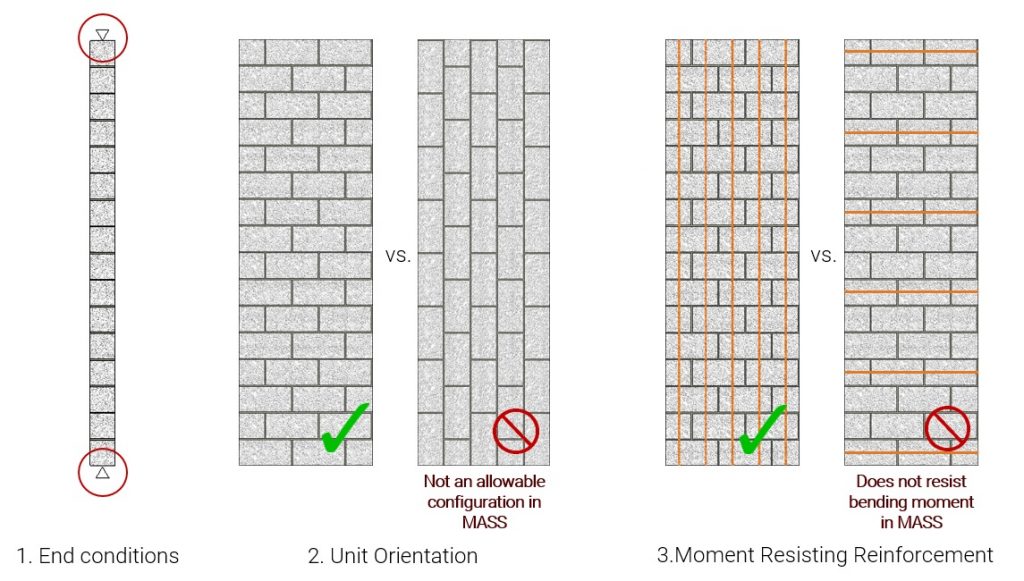
- The wall is supported at the top and bottom
- The masonry units are placed horizontally, with the bed joint parallel to the ground
- Moment resisting reinforcement is placed vertically in the masonry cells
Even with these constraints built into the software, it is possible to accurately analyze and design a horizontally spanning wall using MASS.
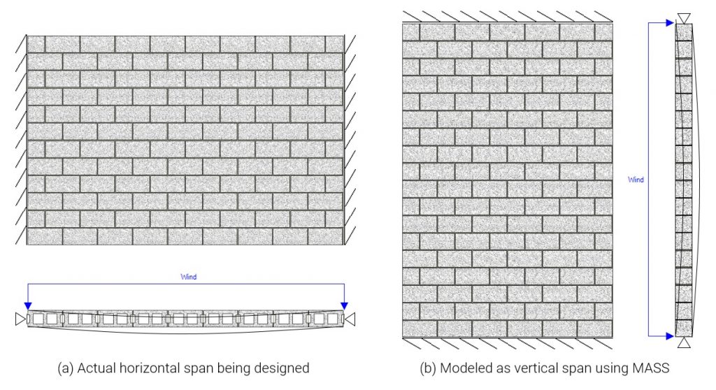
Assemblage Geometry
When designing a horizontal span using MASS, there is no way to change the orientation of the entire wall. As mentioned above, the supports are always placed on the top and bottom of the wall so to account for this, the actual wall being modeled must be rotated 90 degrees to turn a horizontal span to a vertical span within MASS. This same principle applies to the span length, which must be input in MASS as the wall height.

When making the 90 degree rotation, everything about the wall is rotated – including the orientation of the bond pattern! This leads us to the next item in need of consideration…
Masonry strength in relation to bond pattern
Unless you are building a wall with units stacked on their sides, there is no way to alternate the bond pattern within MASS to have the software automatically take this into account on your behalf.
Unlike poured concrete, masonry assemblages do not have the same tensile and compressive physical properties in all directions. The direction of the bond pattern matters and is taken into account within the CSA S304 design standard for both unreinforced and reinforced masonry.
Unreinforced walls in bending depend on tensile strength
The bending capacity of horizontal spanning walls is generally governed by the tensile strength of the masonry assemblage, ft (See note below for exceptions). Vertically spanning walls have a continuous bed joint where a crack is likely to form without intersecting the unit itself. This results in the vertically spanning tensile strength being less than that for horizontally spanning walls, working to your advantage by increasing the wall’s bending capacity!
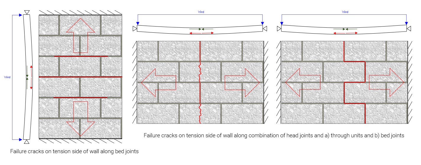
This is taken into account in the CSA S304-14 in Table 5 where the distinction is made between tensile strength normal and parallel to the bed joint.
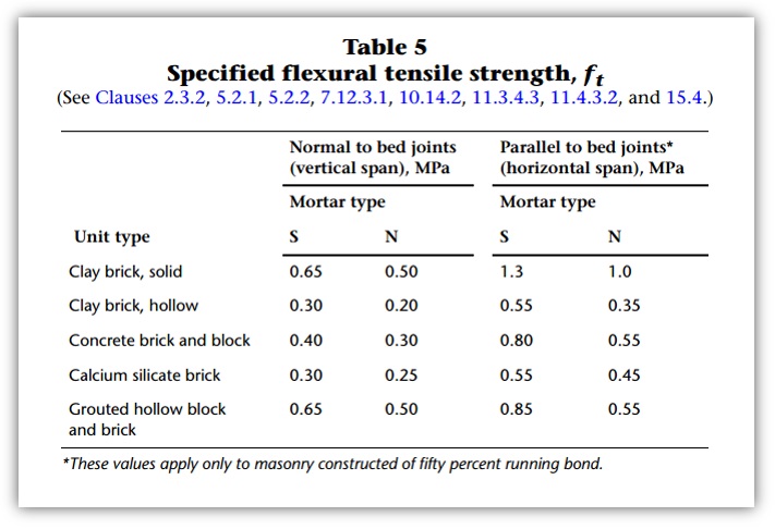 Note the bottom * indicating that these only apply for 50% running bond pattern. Sorry stack pattern fans! You’re stuck using 0.40MPa.
Click here to see S304-14 Table 5 full notes
Click again to hide expanded Table 5 notes.
2014 edition is shown here and has not been changed from 2004.
Changing tensile strength in MASS
You can account for this change within MASS by unchecking the “Auto” functionality and manually typing in the correct value to be used in your design.
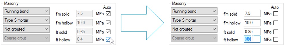
For example, if designing an unreinforced block wall, the corresponding Table 5 value for ft is 0.80MPa for horizontal spans. Since the default value MASS would normally use for a vertical span is 0.40MPa, the “Auto” box can be unchecked and 0.4MPa can be replaced with 0.8MPa.
Keep in mind that when “Auto” is deselected, all 4 values must be entered, including the ones that may not be relevant.
Note: Due to the nature of horizontally spanning walls having little or no applied axial loads, unreinforced walls spanning horizontally are typically governed by tensile strength. As is the case for vertically spanning unreinforced walls, there are other failure modes that must also be considered (linear compression of masonry, maximum allowable eccentricity, and ultimate compression at failure) however these all become important with the presence of applied axial load. Provided that there is no axial load and 0.6f’m is greater than ft, failure of the extreme tensile edge will govern the wall’s capacity.
Reinforced walls in bending must have their compressive strength adjusted as well
The introduction of reinforcement to your design allows the wall to bend well beyond its linear elastic capacity crack and have all tensile forces resisted by horizontally placed steel. The ultimate compression strength that couples with this steel still needs to be manually adjusted to take into account the direction of compressive stress relative to the direction which f’m is based upon. The CSA S304 standard uses the chi factor to accomplish this in clause 10.2.6.
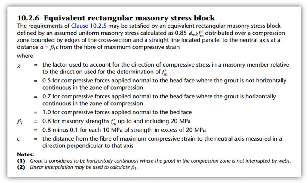
While MASS assumes that the head joint is perpendicular to the supported edges, it is in fact parallel for a horizontally spanning wall which must be taken into account by chi which ranges from 0.5 to 1.0, seen below:
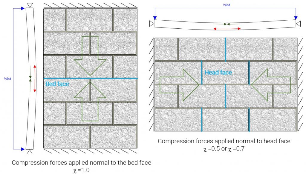
For horizontally spanning walls, any compression force that is coupling with reinforcement must use the correct value of the chi factor which for vertically spanning out-of-plane wall is always 1.0. Click here to read more about the chi factor and masonry beam design. Whether or not the correct chi value is 0.5 or 0.7 depends on whether the compression zone exceeds the face shell thickness, extending into the grouted cells. MASS automatically changed chi for beam design as beams are within the originally intended scope of MASS. For horizontal wall spans, it must be manually checked. Using 0.5 without checking is conservative but taking advantage of chi = 0.7 is very easy to check. Upon completing a moment and deflection design, multiply the neutral axis depth, c, by Beta1 (0.8 for nearly all cases) and compare that value to the thickness of the masonry unit face shell thickness.
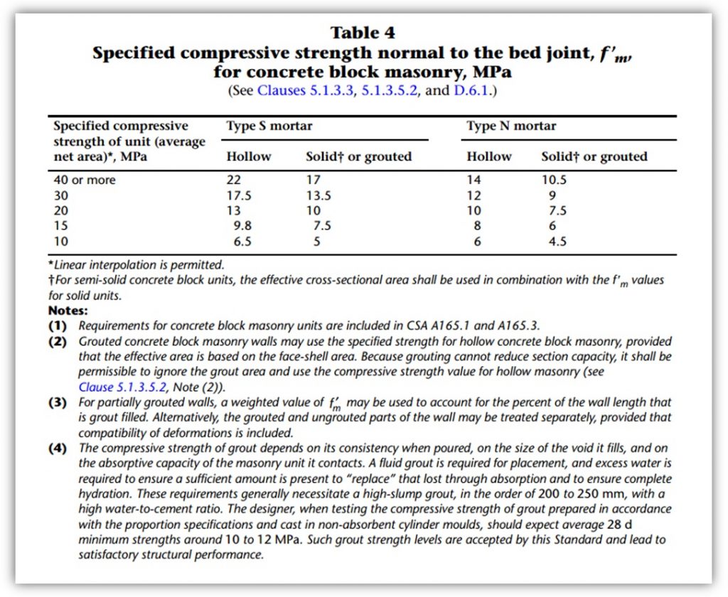
Table 4 is shown below for quick reference of f’m values before the chi reduction factor is applied:
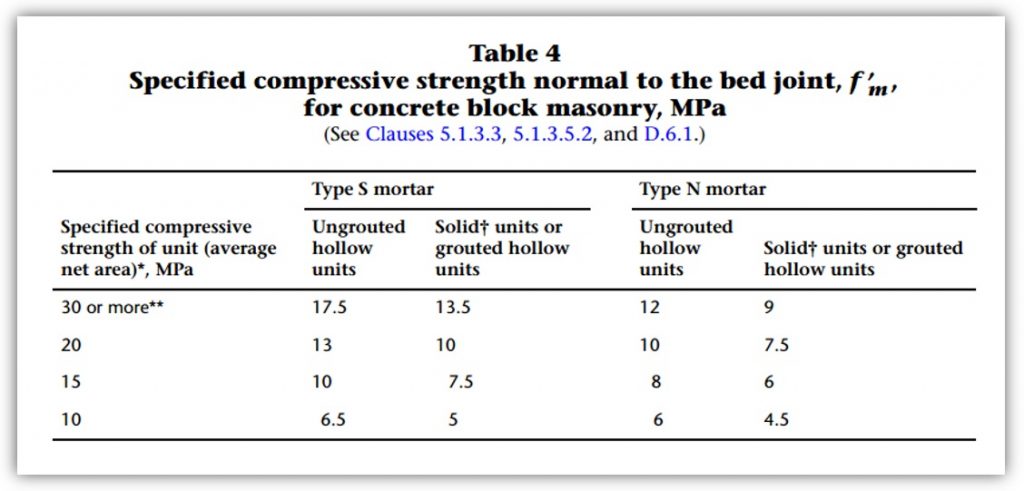
Click to view Table 4 Notes as well as 2004 edition
Click again to hide expanded Table 4 notes.
Table 4 has been slightly changed from the 2004 edition. One change in particular is the increase in hollow strength of a 15MPa unit from 9.8mPa to 10.0MPa.
Changing compression strength in MASS
The reduction in f’m can be taken into account by unchecking the “Auto” selection box for masonry strength and manually typing in the adjusted value. For a 15MPa block, the corresponding grouted compressive strength is 7.5MPa (Table 4, above) and the reduction factor, chi, for interrupted grout is 0.5. To account for this in MASS, a custom grouted strength of 3.75MPa can be entered. In the event that the compression zone does not extend into the grouted cells, it is better the ignore the effects of grout and use only the compressive strength of the bonded face shell area. Not only can you take advantage of using a higher f’m value, but you also no longer have any interrupted grout and a chi value of 0.7 can be used. For that same 15MPa unit, hollow f’m is 10MPa (Table 4, above) so to account for this in MASS, a custom hollow f’m value of 7MPa can be specified.
Continuing from the earlier unreinforced example, these changes can be made to MASS by changing the solid and hollow custom f’m values.
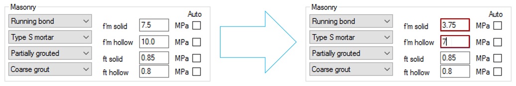
MASS automatically assigns hollow and grouted f’m values to each part of a partially grouted wall cross section. By applying a reduction of 0.7 to the hollow strength and a 0.5 reduction to the grouted strength, MASS will correctly take each chi factor into account. As a bonus, MASS will also check the capacity of the wall ignoring the effects of grout which can will provide an even higher moment resistance for cases where the compression zone extends barely beyond the face shell.
Once this change is made, MASS will use the entered values rather than using the ones from CSA S304 Tables 4 and 5.
Axial Load
As is always the case for regular wall design, axial loads (dead, live, snow, and wind uplift) work in combination with the internal coupling stresses of masonry in compression and steel in tension to resist out-of-plane loading. A key difference for horizontal spans is that unless there is an applied horizontal compression force on the wall, the internal forces resisting bending are acting perpendicular to the vertical axial loads (including self-weight). When determining the strain profile at failure for bending in the horizontal direction, there is no added compression force resisted by the cross section to resist applied axial loads.
Ensuring zero axial load in MASS
At first glance, this sounds like something that doesn’t need added consideration. After all, how difficult is it to not apply axial loads? The thing to keep in mind is that MASS automatically calculates and applies self-weight to wall designs by default. To perform a design with a factored axial load of zero, simply uncheck the self-weight option at the bottom of the MASS Loads tab and check that your Pf and Pr values are actually 0.0kN.

Check wall in vertical direction
If there are vertical loads applied on the horizontally spanning wall, the wall must still be able to resist those loads as well as the corresponding accidental eccentricity in accordance with CSA S304-14: 7.7.3 or 10.7.2 for unreinforced and reinforced walls, respectively:
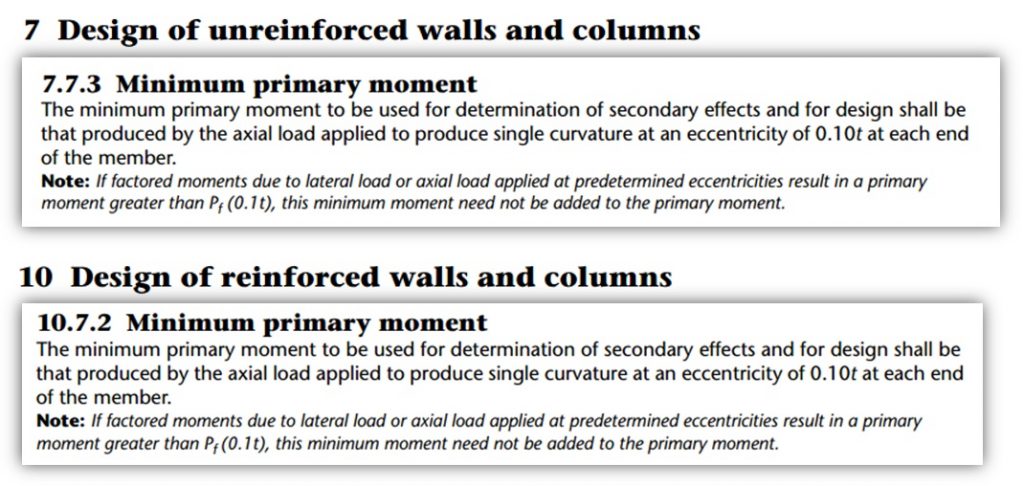
This means creating a new wall design where the wall is modeled normally (height of horizontally spanning wall is actually input as the height – imagine that) with only the axial loads applied. MASS will take these minimum primary moment clauses into account on your behalf when checking the wall.
Final Summary
As a quick and easy recap, three key aspects of horizontal bending can be considered to design horizontally spanning walls using the MASS Walls module.
-
Assemblage Geometry
-
Rotate the wall 90 degrees and enter the horizontal span as the height in MASS
- While MASS thinks it is designing an effective m length of wall, making this adjustment allows MASS to be useful for designing an effective m height of wall
-
-
Masonry Strength relative to bond pattern
-
For unreinforced masonry, manually adjust ft in MASS based on CSA S304-14: Table 5
- Hollow ft can be increased from 0.4MPa to 0.8MPa and grouted ft can be increased from 0.65MPa to 0.85MPa.
- This only applies to 50% running bond (stack pattern exempt)
-
For reinforced masonry, manually adjust f’m in MASS based on CSA S304-14: 10.2.6
- Hollow f’m in MASS must be reduced, multiplied by chi = 0.7
- Grouted f’m in MASS must be reduced, multiplied by chi = 0.5
-
-
Axial Loads
-
Ensure that factored axial load and axial load resistance are both zero
- Uncheck the apply self-weight option in the loads tab which is enabled by default
-
Confirm that wall still has adequate capacity to resist the applied vertical loads.
- Create a new wall module with only axial loads applied to check capacity in the vertical direction
-
Upon taking these items into consideration for your design, designing walls that span horizontally is a breeze!
As always, feel free to contact us if you have any questions at all.
CMDC is the authorized service provider for the MASS software which is a joint effort of between CCMPA and CMDC.