Adding steel to a wall design does not necessarily mean that the steel is being used. How to avoid adding steel that offers no benefit
The CSA S304-14 divides masonry wall design into two separate chapters depending on whether or not the wall is reinforced. Chapter 7 and chapter 10 govern the design of unreinforced walls and reinforced walls respectively. Since steel cannot be used in compression without being laterally tied to prevent buckling, it is ignored for all design calculations which opens up a “grey” area. Walls can be vertically reinforced with the steel doing nothing from a capacity and moment resisting perspective if the bars are not in tension. It is these cases where the steel is ignored and the wall is designed as if it were unreinforced.
How to tell when a wall is designed with the reinforcement ignored
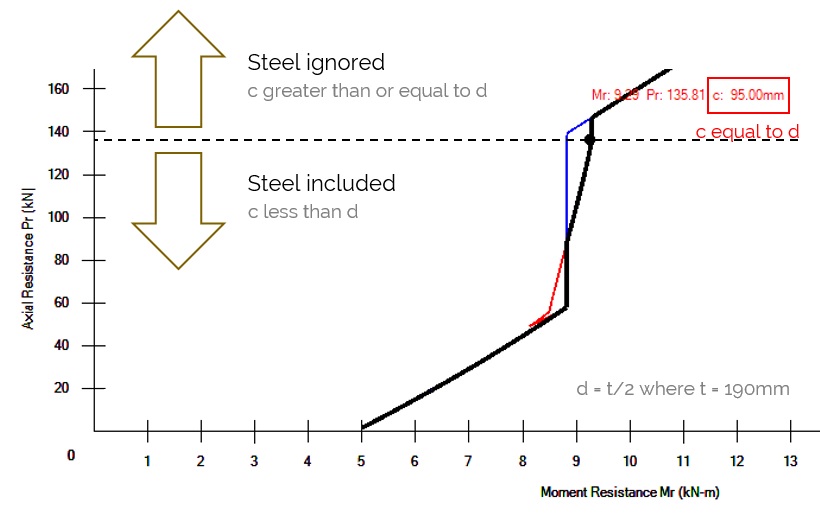
For a bar to be included, it must be further away than the neutral axis from the extreme compression edge of a wall and therefore in tension. Since the neutral axis location is a function of axial load (and the area of masonry required for the compression block to equal the axial load plus tensile force in the steel), there is a break even point where any marginal increase in axial load shifts the neutral axis beyond the depth of reinforcement. MASS solves for this point where the steel is no longer in tension and saves the corresponding axial loads and moment as Mtension and Ptension. For example, bars placed in the middle of a 20cm unit (thickness of 190mm) are 95mm away from the compression edge. Axial loads that result in a neutral axis, or c, location of 95mm or higher ignore the effects of steel in the design.
No. 15 bars placed at 1200mm in a partially grouted 20cm, 15MPa unit
Conversely, axial loads resulting in a c value that is less than d result in designs which include the added effects of reinforcement.
Skill testing question
Is it possible to have a wall that both ignores and includes the effects of reinforcement at the same time but for different load cases?
Decide for yourself and then click to expand the answer
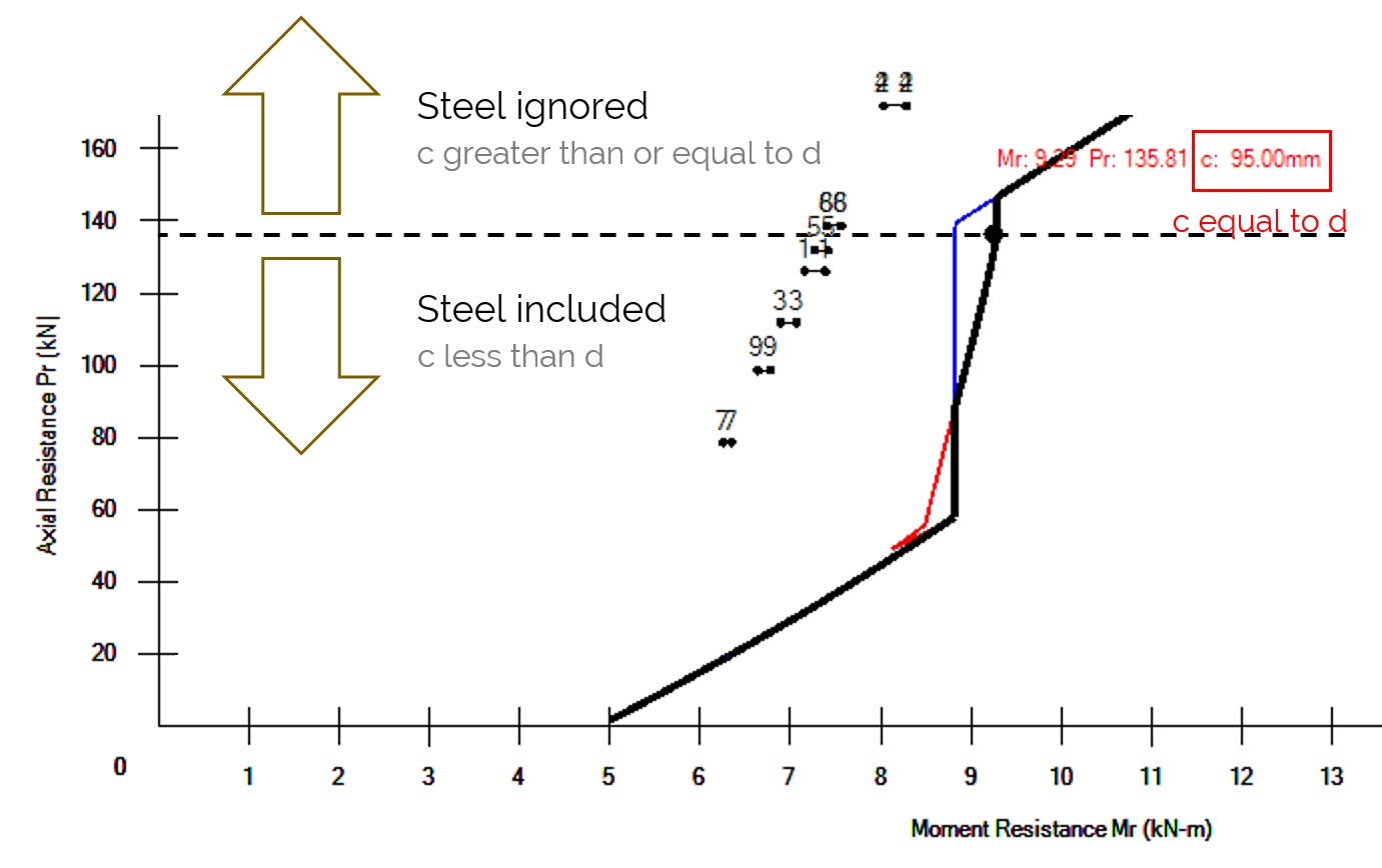
Yes! While the envelope curve itself is constant for a cross section, independent of loading, some load cases can fall above and others below the axial load at which reinforcement is no longer in tension, Ptension. This actually happens more frequently than you might think. The critical load case may be the one with the highest factored lateral load with a lower axial load (0.9D instead of 1.25D for example). While all of the results in MASS (or hand calculations) rely upon the steel being in tension, a non-critical load case (let’s say, 1.4D) may be above this threshold.
Where to check this using MASS
This can be checked in MASS in two places. The first is at the bottom of the Simplified Moment Results, where there a table showing how MASS arrives at a total factored moment for each load case. The Simplified Moment Results table corresponds to the example shown in the interaction diagrams above.
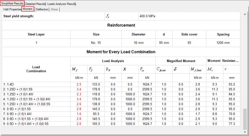
All load cases that result in a neutral axis location less than d (95mm in this case) use the reinforcement in tension. From looking at the table above, reinforced analysis is used for load cases 1, 3, 7, and 9.
The other place to find this information in MASS is on the actual interaction diagram drawing. Each load case can be clicked on to reveal the following information:
- Mf,p – Primary factored moment (kN*m)
- Mf,tot – Total factored moment (kN*m)
- Mr – Moment resistance (kN*m)
- Pf – Factored axial load (kN)
- c – Neutral axis location (mm)
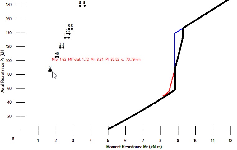
Load combination 7 selected displaying corresponding summary information.
“Am I benefiting by adding steel to this wall?”
While a design may be designed as reinforced, where the steel is in tension and adds to a wall’s moment resistance, that does not mean that the steel is needed. Looking at the interaction diagram above, and where each load combinations lies to the region of the wall can offer insight into how the wall is behaving and which mechanism governs its failure at ultimate conditions.
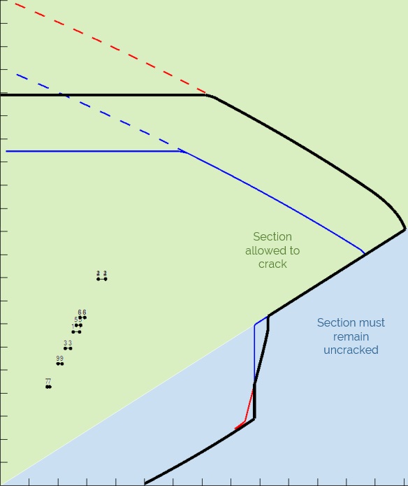
Cracking restrictions based on limiting eccentricity of an unreinforced wall with the envelope curve of a reinforced wall.
The main benefit of vertical steel to the moment capacity of a wall is in the blue region of the figure above, where otherwise the wall would not be permitted to crack and rely on the tensile strength of masonry. Generally, load combinations with high lateral loads and lower axial loads fall within that region and benefit from the added steel. The example used in this post highlights an instance where the lateral loading is relatively small (Ex. low net internal wind pressure) and the reinforcement is not needed to satisfy the wall’s capacity requirements.
As written about in another post, there can be other reasons why MASS is adding reinforcement to a wall. However, it should be noted that by starting with the default masonry unit and reinforcement selections, MASS will first return a successful unreinforced design and only after the disabling the unreinforced selections will MASS add “unnecessary” steel to a wall design.
There are perfectly valid reasons to add steel to the wall design in this example that are outside the scope of a MASS wall module such as when the wall is acting in a system with other reinforced walls. The important thing is that the designer fully understands why the software returns the results that it does and what the reasons are for doing so.
As always, feel free to contact us if you have any questions at all. CMDC is the authorized service provider for the MASS software which is a joint effort of between CCMPA and CMDC.