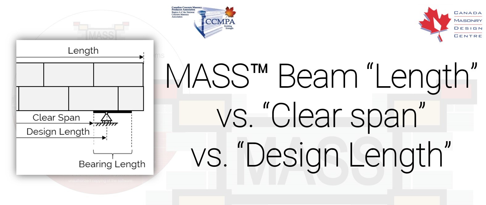
When creating a new beam in MASS, it can initially seem confusing to be shown so many different terms regarding lengths and spans. This post breaks down the difference between a beam’s length, clear span, bearing length, and design length, explaining the background and purpose for each.
Length
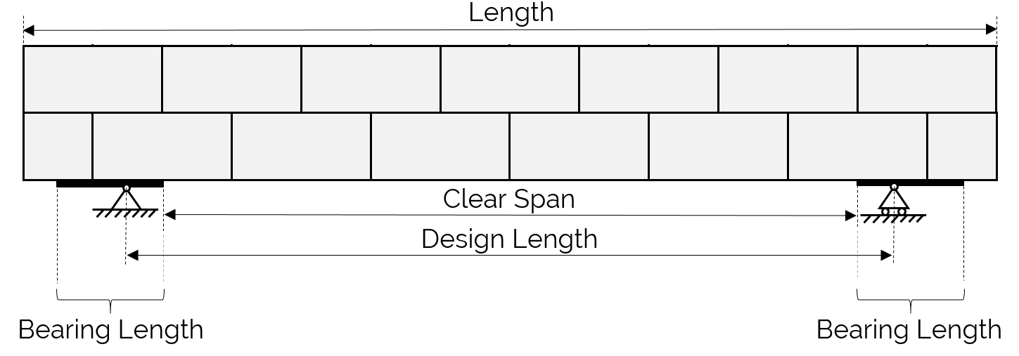
A beam’s length represents the total length of the entire modeled assemblage including any overhanging length on the outside edges of the supports. This value is typically entered in first and must accommodate the length of the opening above which the beam is spanning as well as the bearing plates on either side. Any additional masonry outside of the primary span is not used when distributing loads and determining the factored moment or shear that must be resisted by the beam. Once specified for a new beam design, a clear span,explained below, is then assumed based on the length needed for bearing on either end.
Clear Span
The clear span refers to the length of the opening above which the beam is spanning. While a beam’s length is typically entered first into MASS, it is also possible to start a MASS design by specifying a clear span and let the software automatically fill in the total beam length based on the length required for bearing on either side, rounded to the nearest modular cell length.
Bearing Length
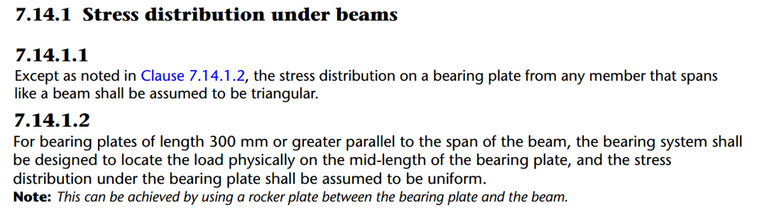
The bearing length is defined as the length along the beam under which a high concentration of stresses due to concentrated loads is transferred to the supporting structure below. It can be spread over a steel plate or an area of masonry under compression. The default bearing length of 300mm was chosen for MASS because it is the longest allowable bearing length (CSA S304-14: 7.14.1.2) that can use a triangular load distribution and not require additional detailing (ie. using a rocker plate) to ensure a rectangular load distribution. For triangular reaction distributions, the centre of reaction is at one third of the bearing length away from the edge of the clear span and for rectangular distributions, the distance to centre of reaction is at half of the bearing length.
Design Length
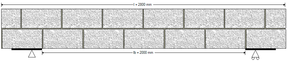
Design length is the distance between the centre of reactions between beam supports. It is less than the beam length and greater than the clear span, used to determine the factored moment and shear. For example, checking MASS results by hand and looking to replicate the maximum factored moment at mid-span for a simply supported beam, the design length is used in Mf = wL2/8.
Quick demonstration – From masonry elevation to design using MASS
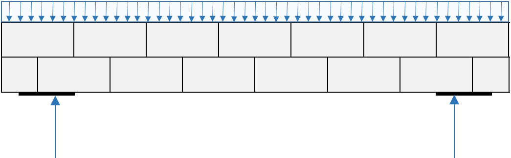
Starting with an elevation containing an opening with masonry extending above and on either side, a portion must be designated as part of the modeled beam. This example where two courses are assumed for the beam’s height, the full beam length extends one full masonry unit to either side which allows room for the bearing area in addition to the clear span.
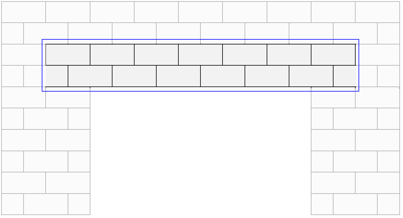
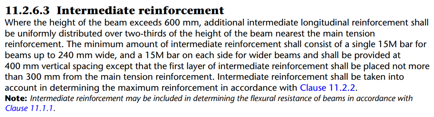
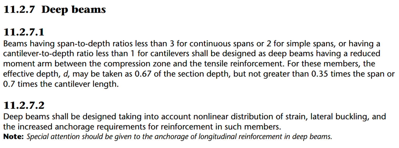
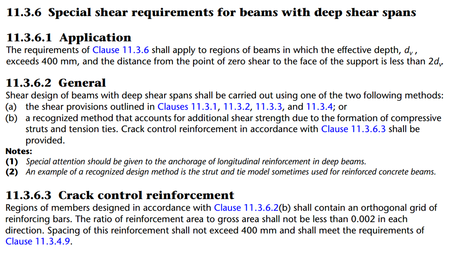
For the same elevation, it is also possible to design a single course beam or go all the way up to four courses which can all result in acceptable solutions. Smaller beams have reduced moment capacity mainly from a smaller moment arm between coupling tension and compression forces while taller beams can have intermediate steel requirements (S304-14: 11.2.6.3) and may also have to satisfy additional provisions for deep beams (S304-14: 11.2.7) and deep shear spans (S304-14: 11.3.6). Choosing how a beam is modeled is left to the discretion of the designer.
For all masonry beam designs, a load path for vertical loads must be assumed for transfer to the supporting structure below. The default bearing area with a bearing length of 300mm is shown below resulting in a triangular distribution of the reaction force. Had the bearing length been longer than 300mm, the reaction would have been spread over a rectangular distribution (S304-14: 7.14.1.2).
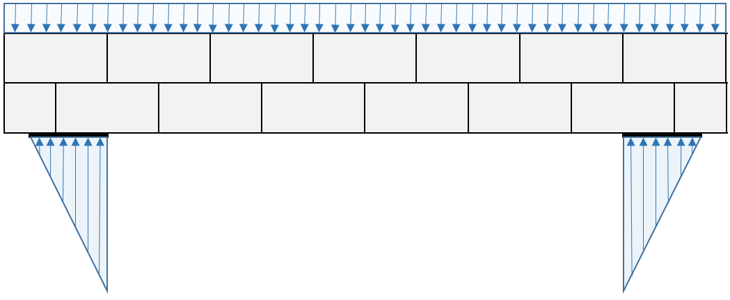
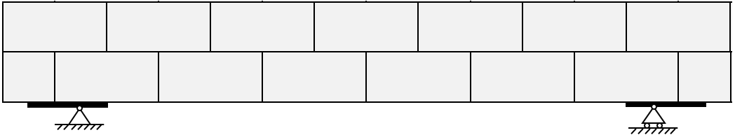
In order to determine the design length, the centre of each reaction force must be determined. For a triangular reaction distribution, this location is one third of the bearing length away from the edge of the clear span for each support. (Rectangular distributions have a centre of reaction point half way through the bearing area)
The locations of the reaction forces expressed as point loads is then used to determine the design span. They are also where MASS draws the support points underneath the bearing plates in beam drawings.
Note that the difference in unit arrangement between the figures above and MASS has no impact on the design as fully grouted masonry. MASS always starts an assemblage with a full unit however starting with a half unit as was done in the illustrations above is functionally the same design.
Click to expand all referenced CSA S304-14 clauses
Taken from the 2014 CSA S304 masonry design standard, Clause 7.14 dictates the stress distribution that is to be used for transferring loads from a beam support to the wall below.
Clause 11.2.6.3 specifies the placement of intermediate reinforcement which is handled automatically by MASS. There is no option to disable intermediate reinforcement as that would result in designs that are not in compliance with the CSA standards.
In evaluating whether the “deep beam” classification is warranted for a design in MASS, the clear span is used in determining the span-to-depth ratio.
The edges of the clear span are also used in checking clause 11.3.6.
As always, feel free to contact us if you have any questions at all. CMDC is the authorized service provider for the MASS software which is a joint effort of between CCMPA and CMDC.