Understanding how this resource it meant to be used, and helping you identify when your situation is beyond its scope.
This page outlines the limitations in more detail with figures and examples to help clarify how to use it.
This page outlines the limitations in more detail with figures and examples to help clarify how to use it.
To make the most out of the Partition Wall Calculator, it’s important to grasp the limitations and basic ideas that shaped its creation. This tool provides engineering design results based on a series of inputs and assumptions that were made so this tool could be applied to a wide range of applications.
This article breaks down these limitations and assumptions so that designers have a clear understanding, empowering them to make well-informed choices when using the calculator for their designs. Additionally, designers should be mindful of the disclaimer linked to the calculator’s use.
Directly analyzing the exact wall configuration and loading will always provide the most efficient solution at the end of the day.
The limitations chosen here are intended to capture many of the most common applications but the line had to be drawn somewhere. Accommodate more penetrations or higher fixture weights and maximum heights are reduced. Maximizing allowable heights by restricting openings or finishing means that very few real-world situations are included. This resource strikes a balance in the middle.
It can easily be done! Just not using this tool.
Not a problem! This tool just can’t help in this case. Analyze the wall using the specific details to evaluate whether a particular configuration is acceptable.
If the wall is unreinforced then no problem – just make sure it is constructed in accordance with CSA A371.
Reinforced walls are a different story. While stack pattern construction can be perfectly fine, the behaviour is slightly different compared to 50% running bond. Can you design stack pattern partition walls? Absolutely, and it’s very easy using software! Can you do it using the results from this tool? Unfortunately not, as we did not take this particular aspect into account.
No reason why it can’t be designed or checked! Just don’t use this tool for these situations because only scenarios where a maximum portion of the wall was compromised by openings were considered.
Finishings can be attached to one or both sides of the wall, as long as the total weight doesn’t exceed 30 kg/m2 on each side. To give a general idea, this is roughly the weight of a 12 mm thick adhered porcelain tile.
The design results consider that 30kg/m2 is adhered to only one side of the wall. This is the largest impact possible as the weight is not balanced and causes an over-turning moment on the wall.

Most walls will have some type of fixture attached to them. Cabinets, TV’s, decorations, etc. The partition wall tool incorporates the weight of fixtures when it runs the analysis. Fixtures attached to walls can be quite heavy and be located far from the centroid of the wall. This can create very large overturning moment in the walls so the weight and location of fixtures are limited when using this tool. The effect of overturning moments is much higher in unreinforced walls so two different sets of limitations for fixtures were created. One limitation for unreinforced walls and one limitation for reinforced walls.
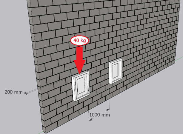
Fixtures, equipment, or any items to be affixed, fixed, or anchored to one or both wall surfaces of the wall must maintain a horizontal spacing greater than 1000 mm and there cannot be any fixtures located above window or door openings.
The weight of fixtures is limited to from the surface of the wall for unreinforced partition walls. In the Figure 1 (a) below, a wall featuring fixtures positioned 1000 mm apart can be observed. These fixtures weigh 40 kg each, with their weight centroid located 200 mm away from the wall’s surface.
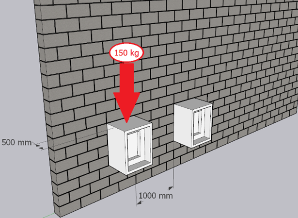
The weight of fixtures is limited to 150 kg with the center of the weight limited to less than 500 mm from the surface of the wall for reinforced partition walls. In the Figure 1 (b) below, a wall featuring fixtures positioned 1000 mm apart is observed. These fixtures weigh 150 kg each, with their weight centroids located 500 mm away from the wall’s surface.
Partition walls designed using this tool are required to have a suitably rigid base to support the weight of the wall and also requires lateral support. For walls that span vertically, there would need to be lateral support anchors at the top of the wall. For walls that span horizontally there needs to be lateral support anchors at both sides of the wall. It is important to note that for horizontally spanning walls, the maximum height calculated using this tool would actually be the maximum length for a horizontally spanning wall.
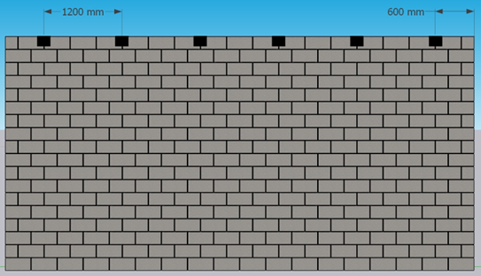
For a vertically spanning wall the lateral support clips are required to be spaced at 1200 mm apart horizontally with lateral support provided within 600 mm of each end of the wall. For example, a wall with lateral support clips placed at 800 mm from the end and spaced 1000 mm apart horizontally do not satisfy the above condition and cannot be designed using the partition wall tool.
In Figure 2 below, partition wall anchors positioned according to these specified limitations is observed.
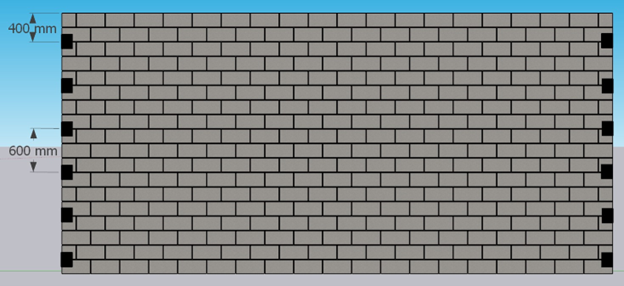
For a horizontally spanning wall the spacing requirement is more strict and the lateral supports are required to be spaced at 600 mm with lateral support within 400 mm of the top of the wall. For example, a wall with lateral support clips placed at 200 mm from the top or bottom and spaced 400 mm apart vertically satisfies the above condition and can be designed using the partition wall tool.
In Figure 3 below, partition wall anchors positioned according to these specified limitations is observed.
Partition walls are non-loadbearing walls. They are designed solely to support their own self weight (and finishes and fixture) and are not designed to resist any lateral load.
A gap at the top of the partition wall will ensure that no additional vertical loads can be transferred into the partition wall. Also, in the case of roughened concrete, not providing a gap will allow the building to transfer shear loading into the wall, causing the partition wall to become a shear wall. The size of the gap at the top of the partition wall is dependent on structure above and any anticipated deflection.
A detail that is commonly missed with partition walls is to provide a vertical gap between the ends of the wall and an abutting column or loadbearing wall. When the wall is constructed tight, the wall will become engaged when the building deflects and creates an infill wall. These partitions were not designed as infills, so a gap is very important. The size of this gap is based on the height of the wall and the anticipated storey drift.
Concrete Masonry Units (CMU) that are used in the design of the partition wall are required to adhere to the specifications outlined in CSA A165. The partition wall tool requires units to have a minimum compressive strength of 15 MPa and a minimum density of 1700 kg/m³. It is imperative to note that Type D units are expressly prohibited when using the partition wall tool. Furthermore, the mortar designated for partition walls in this calculator is required to be Type S, in conformity with the provisions delineated in CSA A179.
In the process of designing a reinforced partition wall with this partition wall tool, the blocks must be arranged in a 50% running bond configuration. It is expressly prohibited to arrange the blocks in a stack pattern or decorative bond when utilizing the partition wall tool for reinforced partition wall design.
Conversely, when dealing with unreinforced masonry partition walls, a certain degree of flexibility is afforded. In this partition wall tool, unreinforced walls are allowed to incorporate stack patterns and/or decorative bonds, provided that they function as vertically spanning walls (horizontal spanning is not allowed). Additionally, it is imperative to ensure compliance with the minimum joint reinforcement requirements as outlined in CSA A371.
When designing partition walls, it becomes apparent that there are distinct considerations regarding their potential to span horizontally. When employing the partition wall tool, reinforced masonry partition walls are not allowed to be designed to span horizontally. Conversely, unreinforced masonry partition walls can be designed to span horizontally between lateral supports only if they are built in 50% running bond (no stack pattern or decorative bonds are permitted).
In the context of horizontally spanning partition walls, the necessary details concerning lateral support connections can be found here. These requirements serve as a guide for establishing robust connections that facilitate the desired horizontal spanning capability.
Furthermore, when designing horizontally spanning walls with the partition wall tool, the prescribed maximum height given in the final table of results should be considered as the upper limit for the length of the wall. When interpreting the results table for horizontally spanning walls, the shear force per meter height can interpreted as the shear force per meter length. However with lateral supports spaced at 600 mm instead of 1200 mm, this shear force per meter length shall be divided by 2.
Many partition walls require piping, conduit, and small ductwork to pass through it. The partition wall tool does allow users to have these small penetrations but they are limited to the following requirements.
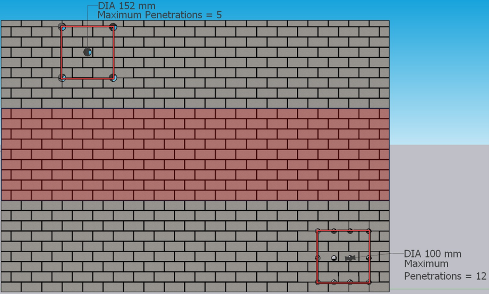
Penetrations in partition walls must not exceed 152 mm (6”) in any dimension at the wall’s face and should not disrupt reinforcing bars. The total area of these penetrations should not surpass 0.1 m² within every 1.0 m² of wall surface, and they are not allowed in the central third of the wall.
In Figure 4 below, two clear examples of creating wall penetrations are shown. It’s worth noting that these penetrations are located outside the central third of the wall. In the top-left cluster, each with a 152 mm diameter, the combined area of all 5 penetrations within 1.0 m² of wall surface is 0.091 m². In the bottom-right grouping, featuring penetrations with a 100 mm diameter, the total area of all 12 penetrations within the same 1.0 m² wall surface is calculated as 0.094 m². It’s crucial to highlight that both sets of penetrations adhere to the specified limitations, as long as they do not intersect with reinforcing bars.
In Figure 4 the shaded red area highlighting the middle third of the wall can be seen. Partition wall design is limited by moment capacity at the mid-height of the wall, this is why penetrations in the middle third are not allowed.
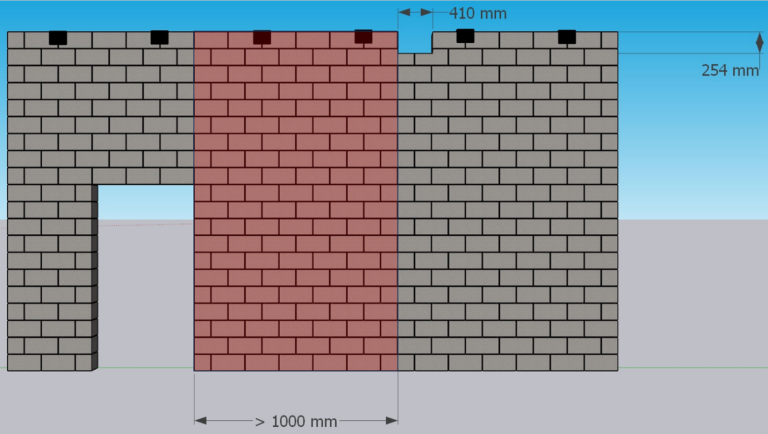
It is common for large ductwork to have to pass through at the top of a partition wall. These openings are much larger than the allowable openings described previously, but the partition tool will still allow for these larger openings. The openings are limited to a maximum height of 254 mm and a maximum length of 410 mm and they require a 15cm or larger unit. The openings cannot interrupt a location of lateral support, and it cannot interrupt any vertical reinforcing. It also must be located at least 1000 mm away from any window and/or door openings.
When your wall has a large penetration as defined in the above paragraph, this will reduce the structural capacity of the wall. To account for this, users of the tool are instructed to select the design choice “Wall has a 1.2m Opening” even if the wall does not have any windows or doors.
PLEASE NOTE: This tool does not detail the support connection at the top of the wall. It is the user’s responsibility to determine if a bond beam is required at the top of the wall, and any impact that this large penetration may have on the detail.
In Figure 5 below, there’s an example of a partition wall with a large opening that sticks to the height and length limits at the top of the wall. This opening is at the top of the wall and doesn’t interfere with the lateral support bracket and is at least 1000 mm away from the opening. Also, take note that a big opening, like the one shown, is only allowed if the unit size is 140 mm or more.
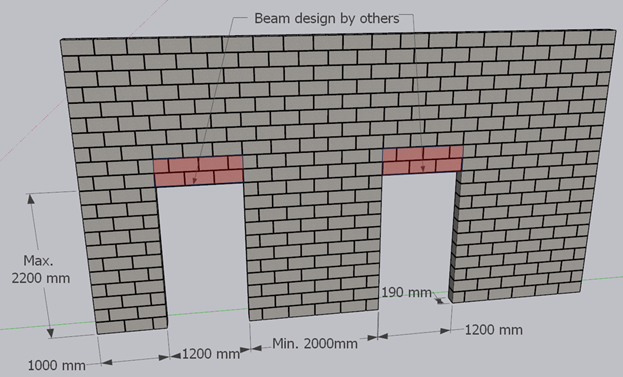
Openings in partition walls for windows and doors are only permitted for vertically spanning walls constructed with units having an actual thickness equal or greater than 140 mm..
In Figure 6 below, two door openings are displayed, extending to the maximum height (2200 mm) and length (1200 mm) constraints. The left opening is situated 1000 mm from the end of the wall, while the distance between the openings is 2000 mm, meeting the minimum requirements. Notably, a 20 cm unit is utilized. It’s crucial to emphasize that, in cases involving openings, the design of beams above the openings is the responsibility of the designer, as this calculator does not incorporate these considerations.
For example, a wall with the distance between openings of 1000 mm cannot be designed with the partition wall tool as it doesn’t meet the minimum requirement of 2000 mm between openings.
The Canada Masonry Design Centre helps members of the design community across the country by connecting them to the resources and supports they need. Contact us today and get the conversation started!
Contact Us© 2026 CMDC. - all rights reserved