Understanding the Total Height input when using MASS can add considerable moment capacity to a shear wall design
If you have ever designed a multi-storey shear wall and wondered why the moment resistance is less than expected, the reason is likely CSA S304-14: 10.2.8:
MASS automatically identifies shear walls that have an aspect ratio less than 1 and designates them as squat shear walls. Keeping all calculations and design results in accordance with the CSA Standards, it also correctly reduces the moment arm of all steel in tension when applicable which is why there is a reduction in moment resistance. While it is often the first reaction of many users to assume that this behaviour comes from a bug in the software, MASS is behaving as intended.
Multi-Storey Applications
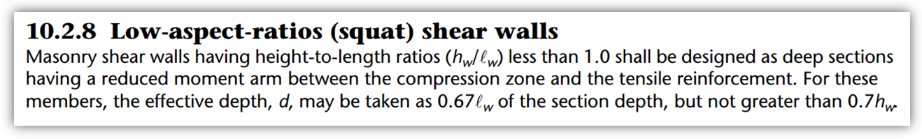
What if you are designing just one element within a larger shear wall where the element has an aspect ratio less than one but the full shear wall does not? Is it correct to be applying the reductions from clause 10.2.8 to elements such as these? Consider the example below:
This example which was used in the Multi-Storey Shear Wall Design article demonstrates an instance where this clause comes into play. The entire shear wall itself is clearly not squat as it’s aspect ratio is 3.2. As it is loaded, it is behaving as a non-squat shear wall so it is not correct to be applying clause 10.2.8 to the design of an individual storey. In order to design this wall in MASS, only the individual elements can be modeled and designed separately. As you can see, the wall input into MASS on its own is designated as a squat shear wall which is where the Total Height input comes in handy: it allows the user to tell MASS that while an element may be “squat”, it should not be treated as such.
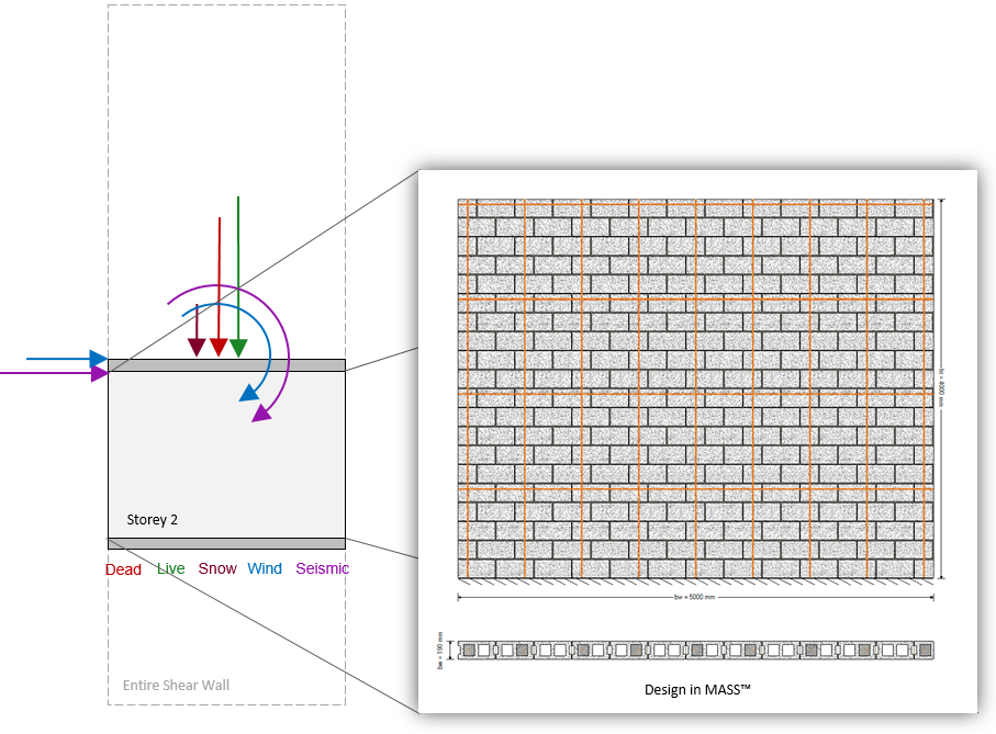
“Height” vs. “Total Height”
The scenario described above is the reason multiple height inputs are available in MASS.
Height refers to the vertical dimension of only the shear wall element being modeled while Total Height refers to the vertical dimension of the full shear wall assemblage, beyond just what is being modeled.
If Storey 2 is modeled in MASS without any consideration of the larger shear wall it is apart of, it is designated as being squat as it’s 4/5 aspect ratio is less than one. When the total height is changed to the full 16m, the aspect ratio used to apply squat reductions from clause 10.2.8 increases to 3.2 and the result is an improved moment resistance.
Impact on Design
How much of a change does this make to a shear wall design? Using the example from earlier, when designing using a 20cm, 15MPa concrete masonry unit, taking the total height into account means the difference between using No. 15 and No. 20 bars placed exactly the same. If using No. 15 bars for both designs, the squat version of the MASS file would need to go all the way from a 15 to 30MPa strength unit to compensate. Furthermore, if the masonry and reinforcement properties were both fixed to the same design, the difference in capacity can be seen on the interaction diagrams below:
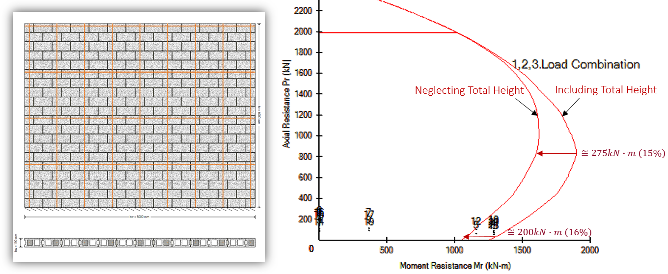
Comparison of moment envelope curves for shear wall design both including and neglecting the total height
For the critical load combination (#15: 0.9D + 1.4W), this means that the moment resistance of the wall is reduced from 1333.5kN*m to 1111.5kN*m, or by 222kN*m, simply by not taking the aspect ratio of the full wall into account!
This effect is further demonstrated in the example below where 70% of the vertical reinforcement is concentrated on either end of the wall. This significant reduction in moment is a direct result of a reduced moment arm for the steel that is in tension and furthest away from the compression zone. Note that this design uses the exact same materials simply arranged differently.
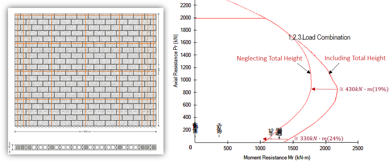
Comparison of moment envelope curves for shear wall design both including and neglecting the total height
There is now a 330 – 430kN*m reduction in the moment resistance compared to the 200 – 275kN*m reduction observed when the reinforcement is evenly distributed. One thing to note for all of these comparisons is that the difference in moment resistance diminishes when the applied axial load approaches Pf,max.
For those curious, a comparison of the uniformly distributed reinforcement and concentrated end steel designs can be found by expanding the section below:
Click to expand 'Uniform' vs. 'Conc End Steel' Design Comparison
Considering that there is no added material or labour required to construct the two designs, the moment resistance benefits are impressive! The next time you have a shear wall design that is governed by moment, try moving more reinforcement to the ends for a boost in moment resisting performance:

Something at least worth considering….
If you have any questions, please do not hesitate to call or email the Canada Masonry Design Centre.
The MASS software is a product of a joint partnership between CMDC and CCMPA. CMDC is the authorized provider for MASS Technical Support.