
Why might joint reinforcement be needed?
Reinforcing masonry walls with wire that is embedded within the mortar joints is quite common. Joint reinforcing can be used for many applications which include, but are not limited to crack control, shear reinforcing, tying together stack pattern masonry, and as flexural reinforcement (to resist horizontal out-of-plane bending).
Many common misunderstandings persist within the design and specification communities as it relates to bed joint wire reinforcement regarding where it’s required, spacing, size, type, and level of corrosion protection. This article provides clarification for designers and contractors as to what requirements should be included within a specification and what requirements should be included within other contract documents, such as structural drawings.
Part of our Masonry Specification Series
Offering recommendations accompanied with background explanatory material to explain how these recommendations were formed. Click here to see the full series.
Disclaimer
The information contained here is intended to serve as educational content for designers, specifiers, or contractors. It is not to be relied upon for formal technical advice, as masonry projects may have details and considerations that are unique to a particular project and may be beyond the scope of the content of this page.
Recommendations
When specifying bed joint wire reinforcement, it is recommended that ladder-type bed joint wire reinforcement should always be used with concrete block masonry. To avoid situations where the bed joint reinforcing will interfere with the vertical reinforcement, truss type bed joint reinforcing should not be specified with vertically reinforced walls.
Corrosion protection is not required for bed joint reinforcement unless exposed to the outside environment (single-wythe walls, veneer walls), or potentially corrosive environments (some industrial settings). In these situations, CSA S304-14 Clause 4.11.3.2 states that the joint reinforcement shall have the same level of corrosion protection that would have been otherwise specified for the ties in CSA A370-14 Connectors for masonry.
Discussion
Specifications should always focus on relaying critical project requirements to the mason contractor. However, providing specific or nuanced design information in a specification may otherwise contradict architectural or structural drawings.
Bed joint wire reinforcement, as with masonry ties, shall not be placed at the discretion of the mason. Their use and placement must be determined from a design analysis and their details must be indicated within structural or architectural drawings. A notable exception to this would be the mandatory requirement that for stack or decorative patterns where the bonding unit overlap is 50 mm or less, in which case the masonry shall be continuously reinforced horizontally with a vertical spacing that shall not exceed 400 mm. In all other cases, bed joint wire reinforcement is something that is only included based on the design requirements established by the architect and/or engineer.
Be careful not to introduce conflicts with other contract documents
An example of a potentially problematic specification that provides specific design information for bed joint wire reinforcement can be seen below:
3.03 INSTALLATION
.1 Concrete Masonry Units with Interior Exposure:
.1 4.75 mm wire, truss type joint reinforcing, hot-dip galvanised, spaced vertically at 600 mm o/c (every third course)
.2 Concrete Masonry Units with Exterior Exposure:
.1 4.75 mm wire, truss type joint reinforcing, stainless steel or equivalent Level 3 corrosion protection, spaced vertically at 600 mm o/c (every third course)
.3 Clay Brick Veneer Units:
.1 3.65 mm wire, ladder type joint reinforcing, stainless steel or equivalent Level 3 corrosion protection, spaced vertically at 600 mm o/c
The following discussion material considers cases in which joint reinforcement may be required, as well as the following properties typically found in the specification: size, type, corrosion protection, and spacing.
Size requirements for joint reinforcement
Clause 8.1 from CSA A371-14 states that wire used for bed joint reinforcing shall have a minimum diameter of 3.0 mm and a maximum diameter of half the joint thickness or 5 mm, whichever is less. In practice, there are two common diameter sizes for joint reinforcing, 3.65 mm (termed “regular”) or 4.76 mm (termed “heavy duty”). In most cases, regular 3.65 mm joint reinforcement is preferred and should be specified because it is easier to cut, install, and lay units on, compared to heavy duty bed joint wire reinforcement. Heavy duty wire is more difficult to work with on site due to its increased rigidity and increased thickness relative to the mortar joint size.
The size of bed joint wire reinforcement required depends on the design. In general, when bed joint wire reinforcement is needed for crack control (e.g., over very long lengths of wall between movement joints, around openings, or as required in stack or decorative pattern masonry) then regular (3.65 mm) size wire should be used. The need for heavy duty wire is typically a result of meeting prescriptive reinforcing ratios for seismic design requirements or resisting in-plane shear forces in loadbearing walls. Therefore, its use must be determined by the designer and detailed within the contract documents.
Types of Joint Reinforcement
There are different proprietary products that function as bed joint wire reinforcing, however, the most common among them are: standard wire, ladder-type reinforcing, and truss-type reinforcing. When two rod bed joint wire is required, ladder type should be specified in most cases.
Single Wire Rod
Standard wire is most commonly used when only a single wire rod is required as joint reinforcing. Per CSA A371-14, Clause 8.1.2: For a wythe of solid masonry units not more than 90 mm thick, single-rod reinforcement may be used and, if so, shall be positioned in the bed joint along the centre of the unit, within a tolerance of ± 13 mm. Otherwise, in all other cases, such as hollow concrete block units, two-rod wire reinforcement shall be used in masonry.
Ladder vs. Truss Type
When two-rod joint reinforcing is required, there are two types that may be specified: ladder- and truss-type. The names correspond to the manner in which cross-rods are seen below:
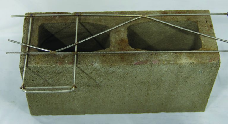
Truss type joint reinforcement with ties for veneer attachment built in.
Not recommended due to potential interference with vertical reinforcement placement
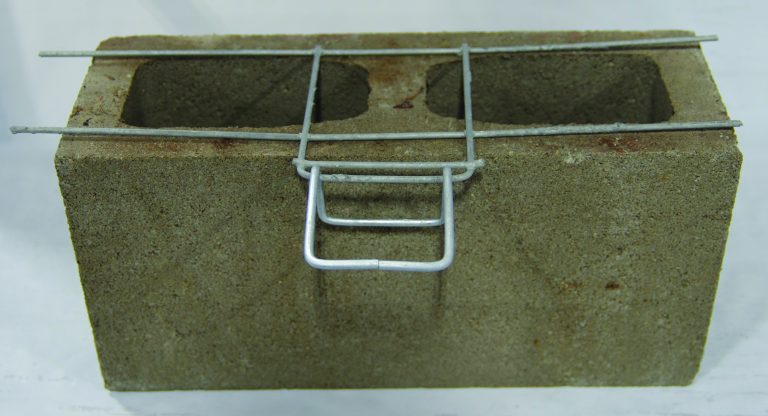
Ladder type joint reinforcement with ties for veneer attachment built in.
Recommended – does not interfere with vertical bar placement
Which type should I be using?
Truss may cause issues, but you can't go wrong with ladder type
When specifying bed joint wire reinforcement for cored clay brick or unreinforced concrete block, truss-type bed joint wire may be used. Truss-type bed joint wire reinforcement is fabricated by securing the cross-rods between wires at an angle to form a truss. The cross-rods will interfere with any vertical reinforcing bar placement in the masonry because of how the cross-rod passes through the open cell (across the middle).
Specifying truss reinforcing in masonry walls that will also be vertically reinforced will create great difficulty in placing the vertical reinforcing. Typical masonry construction practice will have the vertical reinforcing bars placed after the wall is constructed. If there are diagonal cross wires present within the cells it will make the placement of this reinforcing extremely difficult and will likely push the placement of outside of its tolerance window. In some cases, contractors may cut the diagonal cross wires of truss joint reinforcement to facilitate the placement of vertical rebar. However, CMDC generally discourages that practice.
To avoid situations where the bed joint reinforcing will interfere with the vertical reinforcement, truss type bed joint reinforcing should not be specified with vertically reinforced walls.
There is no recognized structural difference between ladder- and truss-type bed joint wire reinforcement. Ladder-type bed joint wire reinforcement has the advantage of locating cross-rods perpendicular to the main reinforcing wires in the face shells. Therefore, cross-rods can be arranged so that they lie on, or close to, unit webs ensuring they do not interfere with vertical bar placement. To alleviate any possible conflicts on site, ladder-type bed joint wire reinforcement should always be used with concrete block masonry.
Exceptions: when truss type can be acceptable
Since vertical reinforcing bars are not easily or typically placed in clay brick or 10 cm concrete block masonry units, truss-type bed joint wire reinforcement may be used. When hollow or semi-solid 15 cm, 20 cm, 25 cm, or 30 cm concrete block masonry units are used then only ladder-type bed joint wire reinforcement should be used. This is the safest approach because of the possibility for these units to contain vertical reinforcing bars, however, truss type joint reinforcement can be acceptable with these types of units when designed and constructed as unreinforced.
Corrosion Protection
Other than for veneer applications, the vast majority of bed joint wire reinforcement used in masonry construction does not require any additional corrosion protection requirements (e.g., plain steel is acceptable and preferred).
Typical bed joint wire reinforcement assemblies (ladders and trusses) are manufactured to be 40 mm narrower than the actual unit width resulting in a mortar cover of 20 mm. CSA A371-14 provides cover requirements for all reinforcing in masonry elements. Except where required for veneer walls, single wythe exterior walls, foundation walls, or interior columns and beams, all reinforcing bars (20M and smaller, without corrosion protection) or bed joint wire reinforcement in masonry walls require only 20 mm of cover from the masonry surfaces.
Designers are reminded that concrete masonry walls (e.g., shear walls and partition walls) are considered to be “interior” when they are located on the inside face of the wall cavity behind the building envelope’s waterproof membrane. These walls are not considered to be exposed to any direct precipitation, or weather, as defined by CSA A371-14. Exceptions can be made, for instances, where masonry is used within certain industrial settings such as a sewage treatment plant, or for other special cases such as for a decorative fountain or pool, etc. when corrosion resistance for interior walls becomes a concern. However, in most applications plain steel embedded with at least 20 mm of mortar cover is sufficient for corrosion protection of bed joint wire reinforcement.
In cases where bed joint wire reinforcement is required in masonry that is exposed to weather (single-wythe walls, veneer walls), or potentially corrosive environments (industrial settings), then CSA S304-14 Clause 4.11.3 requires that the joint reinforcement must have the same corrosion protection as required for ties in accordance with CSA A370-14. Where corrosion protection is required, it should be indicated in the project plans in accordance with the levels of corrosion protection described in CSA A370:
- Level 1: no corrosion protection (plain steel or mill galvanized)
- Level 2: hot-dip galvanized after fabrication (requirements, including coating thickness are indicated in CSA A370)
- Level 3: stainless steel (acceptable grades of stainless steel indicated in CSA A370)
Spacing requirements and whether or not it's needed at all
Spacing requirements for bed joint wire reinforcement are determined by the designer. There is no one-size-fits all spacing requirement for bed joint wire reinforcement. Since it is most commonly required to meet a prescriptive area of reinforcement (e.g., crack control) or to resist in-plane shear forces (e.g., seismic), the size and spacing requirements for bed joint reinforcement are dependent on many possible factors.
Crack control in masonry can be achieved with bed joint wire reinforcement, most commonly in concrete brick and concrete block walls. In such cases, designers may refer to industry recommended guidelines for its use (click here to open in new browser tab) and the recommended methods to determine if and how much may be required. Typically, crack control in very long spans of masonry, or around openings, is achieved by providing a horizontal reinforcement ratio based on net wall area of approximately 0.002. Seismic design requirements for non-loadbearing and loadbearing masonry may also require prescriptive horizontal reinforcement ratios based on the gross wall area per CSA S304-14. However, prescriptive maximum spacing limits and minimum reinforcement ratios may also account for the presence of bond beams. Furthermore, loadbearing walls may be governed by the need for bed joint wire reinforcement to resist in-plane shear forces, which itself may present different prescriptive limits.
Spacing of bed joint wire reinforcement should not be left to the specifications; instead, it should be established during the design of the masonry elements and based on the requirements of CSA S304-14 and CSA A371-14. There are few cases, in addition to stack pattern masonry, where a common size or spacing across all walls is necessary or justified; however, in many cases bed joint wire reinforcement that is added to meet no other definable design objective rationally calculated represents an unnecessary added cost.
Return to Recommendations section. Return to the Specifications page.
Part of our Masonry Specification Series
Offering recommendations accompanied with background explanatory material to explain how these recommendations were formed. Click here to see the full series.
Have a question about anything here?
CMDC is made up of offices across Canada, connecting you with support through our team of technical staff.
Providing clarity and raising issues before they turn into real problems
As part of our overall effort to educate the design community and our contractor members, CMDC has compiled a collection of articles meant to address common areas of misunderstanding or confusion that have resulted in issues in past projects.