When designing a Shearline using MASS, the software relies on you to determine how the wall behaves
The Shearline module in MASS is a useful tool to quickly and easily determine how lateral, in-plane forces are distributed within a single elevation. While the scope of the shearline module is relatively basic and relies upon a number of simplifying assumptions in the analysis, it doesn’t take much time to gain an understanding of how these loads are distributed around openings and movement joints.
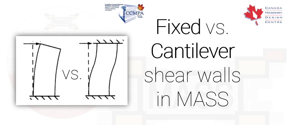
One of the required steps before the loads are distributed is for the user to review the position and geometry of each pier and decide whether it be modeled as “Fixed” or “Cantilever”. More specifically, as an elevation is laterally loaded, whether each element’s deflection would more closely resemble that of a fixed or cantilever shear wall. Below is an illustration of how a shear wall deflects when the top end fixity is left unrestrained, or cantilever (top), compared to a shear wall deflecting with the top end condition fixed, restricting only rotation (bottom).
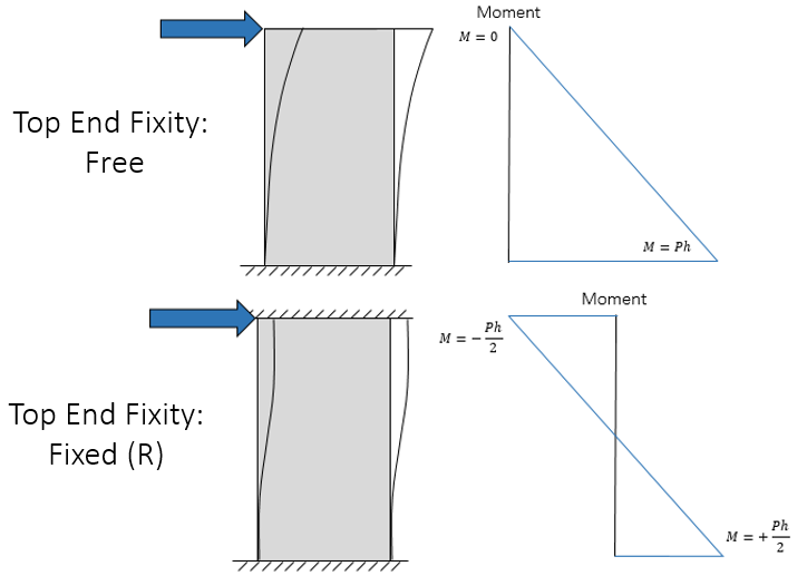
While the difference has a big effect on the design of the shear wall (fixed top reduces factored moment by 50%, two critical sections instead of one), the important aspect when modelling a shearline is lateral stiffness and rigidity. Cantilever shear walls deflect more than those that are fixed from rotating therefore attracting less load relative to the other shear walls within the elevation. An example I posted online a few years ago is included below and runs through the entire process of designing a shear wall elevation using the Shearline module in MASS.
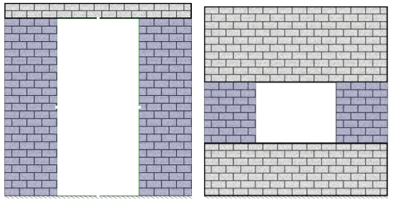
Looking at the example from the video, consider the two piers highlighted below:
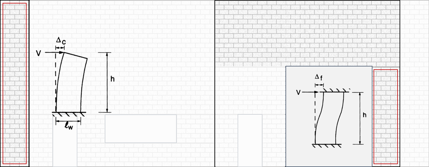
The leftmost pier has nothing above it to restrict lateral rotation so it’s behaviour would more closely resemble that of a cantilever pier. Conversely, the pier on the right has a significant area of masonry which would more likely cause it’s deflected shape to more closely resemble that of a fixed pier.
How to decide of a pier is modeled as a Fixed or Cantilever shear wall
When MASS Version 2.0 was in development, CMDC looked into creating an algorithm that could look at an elevation and automatically designate each element as fixed or cantilever. Unfortunately, development of this functionality did not proceed very far because there was nothing in any building codes, CSA standards, or even consensus within the design community regarding what exactly constitutes fixity at the top of a shear wall. As a result, end fixities were left as direct user inputs, having to be manually assigned by the designer, using their professional engineering judgement, each time a Shearline is created.
Often when there is a difficult engineering judgement, the response it to make the more conservative decision. While there are other design decisions in the development of MASS where choices were made in the interest of remaining conservative, there is no clear-cut “conservative” decision when it comes to lateral load distribution. While a fixed shear wall deflects less (thus attracting a larger shear force due to the increased rigidity) compared to a cantilever shear wall, it is important to remember that lateral, in-plane load distribution is relative. What increases loading for one element will take away from all of the others.
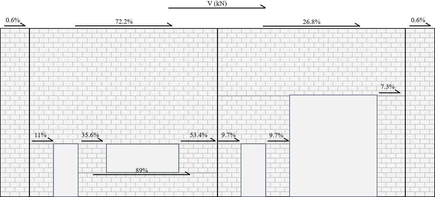
It is no coincidence that the examples shown on the MASS website, in the help files (found by pressing F1 within MASS), in the CMDC Masonry Design Textbook, or shown here highlight cases that are not particularly controversial when it comes to differentiating between fixed and cantilever behaviour. As an example, consider Figure 40 (shown below) from section 6.2 of the MASS Help Files demonstrating a) highlighted piers that would behave as cantilever compared to b) highlighted piers that would behave as fixed shear walls:
The reality is that there are many cases in the middle that can be taken either way with arguments on both sides having valid and rational points. At the end of the day, it is left up to the judgement of the engineer to make the final call.

If you have any questions, please do not hesitate to call or email the Canada Masonry Design Centre.
The MASS software is a product of a joint partnership between CMDC and CCMPA. CMDC is the authorized provider for MASS Technical Support.