While there is no “pilaster module” within MASS, the walls module can be adapted to assist with their design
Masonry Analysis Structural Systems is a versatile tool that can be used to accelerate many different aspects of masonry design. While most design scenarios easily fall within the scope of the software, there are occasionally cases where extra work must be done in order to get useful results from MASS. Pilasters are one such case where their behaviour is similar in many ways out-of-plane walls. In order for the wall module to be useful, the pilaster design must be adapted to fit within the constraints of the user interface.
The method in this post outlined below outlines how the pilaster length can be increased to the length used for wall designs in MASS. The remaining cross section properties can be input into MASS and then all of the loads applied must be proportionally adjusted to factor in the length increase. For example, if a pilaster must be lengthened by factor of 2.5 times its original length, the loads applied must also be increased by that same factor, effectively designing a larger section for a higher load in a way such that the results obtained using MASS are useful in determining the design of the pilaster assemblage. To jump ahead to the final summary at the end of this post, click here.
Disclaimer: By using MASS to assist in the design of a pilaster, it is up to you, the engineer, to ensure that all of the differences between pilaster behaviour and that of a regular masonry wall are properly accounted for within MASS. If there is any doubt of having a complete and comprehensive understanding of how to model these differences, it is best to perform these calculations by hand.
Additionally, while the MASS software is a trusted tool in the engineering community across Canada, all of the liability regarding the results and designs is placed on the end user. If there is any uncertainty as to whether the software is being properly applied, please consult MASS support, the included help documentation, or the end user license agreement. The contents of this article are offered as a resource to be used only if the user is aware that they are no longer working within the scope of the software and do so at their own risk. That being said, the Canada Masonry Design Centre is available to answer any questions about the content of this post.
Getting Started
In order to take into account the differences between a pilaster design and a regular out-of-plane wall design using MASS, there are multiple aspects that must be considered and accounted for regarding:
-
- How the section is modeled (click to jump to section modelling)
- How the loads are applied (click to jump to load application)
This post outlines a process which helps the engineer adapt the scope of the MASS software to the design of pilasters subjected to a combination of axial loads and one-way, out-of-plane bending.
Modeling a “Pilaster” unit using MASS
In order for MASS to be useful as a design tool when dealing with pilasters, it is important to first understand the similarities to an out-of-plane wall constructed using conventional stretcher masonry units. The relevant, shared aspects include face shells with a grouted center region with up to two layers of vertical reinforcement in the middle. While the software can easily design the wall shown on the left but not on the right (below), useful results can be obtained by identifying the common characteristics and applying them within the scope of the MASS wall module.

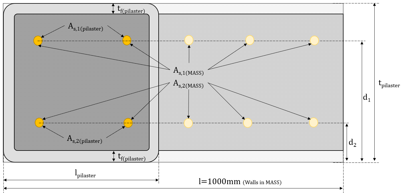
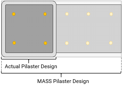
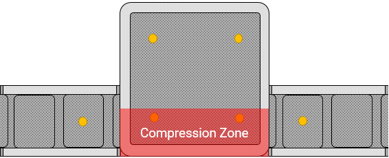
The biggest difference and reason why pilasters cannot be modeled within MASS is that the software performs wall designs exclusively on a per metre basis. While a pilaster is an isolated element within a wall system, it must be adapted to a one metre design length to fit within the wall module. Effectively, the software can only design modules that are exactly 1m in length so the only way to obtain equivalent results is to extrapolate the pilaster length and satisfy this constraint. Displayed below is a diagram of a pilaster superimposed over its corresponding modeled assemblage using MASS:

In order to create a wall design within MASS that will be useful in the design of a pilaster element:
- The wall must be fully grouted.
- The masonry unit geometry must be adjusted to match that of the pilaster unit.
- The reinforcement placement and positioning must be specified to reflect where it would be placed within a pilaster unit
Understanding these three aspects will help ensure that a wall can be created that properly represents the pilaster used for the design.
Fully Grouting the Wall
Since the entirety of a pilaster cross section is grouted, its design in MASS must also be restricted to walls that are fully grouted. This can be changed using the drop down menu along the right side of the MASS input window, shown below:
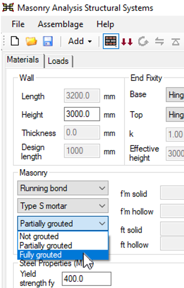
If this is left using the default selection of partially grouted, any designs that do not place a bar in every cell will have a hollow component of all compression-related calculations.
Changing the Masonry Unit Dimensions
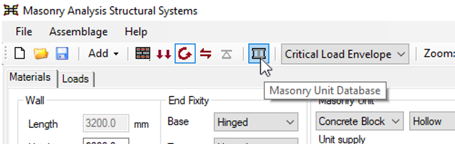
By making use of the Masonry Unit Database, it is possible to create a custom “pilaster” unit which can be used to take into account the different unit size and face shell thickness. The Masonry Unit Database can be found along the top toolbar between the “Bearing Design” button and the “Critical Load Envelope” drop down menu, shown below:
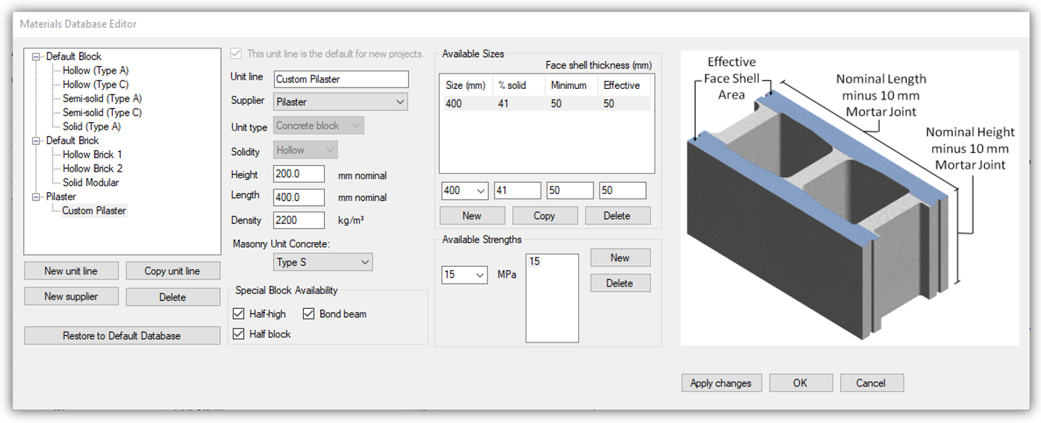
Using this database, a masonry unit with an increased nominal thickness and corresponding face shell thickness can be created and used for design. In this example, a 390mm thick pilaster unit is created (nominal thickness of 400mm)
Click to expand the full process of creating a Custom Masonry Unit
Below is the step by step process to add a new custom pilaster unit to use for design in a MASS wall module (Note: specific values displayed here are not specific to any pilaster unit and the designer should consult with the supplier for values used in design):
- Click the “Masonry Unit Database” icon shown above to open the database editor.
- Click “New supplier“
- Type supplier name: for example, “Pilaster“
- Click “Apply changes“
- Select the new supplier in the list and click “New unit line“
- Enter in the name of the unit: for example, “Custom Pilaster“
- Ensure that it is connected to your new supplier “Pilaster“
- For “unit type” select “concrete block” from the drop down menu
- Ensure that the solidity is set to “Hollow“
- To add a unit size, click “New” beneath the “Available Sizes” table
- Once the default first row has been created, click the “0” entry to select it and click on the drop down beneath the “Size (mm)” column to reveal the available options. Select one and change it to the nominal size of your pilaster unit. Note that the nominal size is equal to the exact size plus a 10mm mortar joint so a 390mm thick pilaster unit would have a nominal thickness of 400mm. The “% solid” column will not be applicable since it is only useful for determining the self-weight of partially grouted walls.
- Change both the “Minimum” and “Effective” face shell thicknesses to the thickness used in your desired pilaster unit. Note that these will affect bar placement but will not impact design results unless the applied axial loads are relatively low as most pilaster designs will result in a compression zone that enters the grouted region of the wall (β1c>tf). Multiple sizes can be created and will appear as check box selections in the input window but there needs to be at least one created to use it for design.
- To add a unit strength, click on “New” just to the right of the “Available Strengths” section and click the “0” PMa drop down to ad a strength that matches that of the pilaster unit used for design. Multiple strengths can be added and will appear as selections in the input window but there needs to be at least one to use it for design.
- Click “Apply Changes” to add the unit to the database. Double check that all of the properties have been specified and click “OK” to close the database editor.
For assistance with creating a custom masonry unit using the database, please contact CMDC, the authorized technical service provider for MASS.
Once the unit has been created, it will appear in the list of suppliers and unit lines under the “Masonry unit” heading in the MASS input window.
Placement and Positioning of Reinforcement
In order to design a wall of a finite length using a MASS wall module that designs walls on a per m basis, all of the properties need to be scaled proportionally to take the different section sizes into account. For example, if designing a 0.4m long pilaster with four 20M bars arranged in a box formation, there is a total of 600mm2 of steel within each layer of reinforcement (1200mm2 total between all four bars). If designing the equivalent 1m section using MASS, this is equivalent to 1500mm2 of steel per layer (600mm2 x 1.0 m/0.4 m) and a total of 3000mm2 of vertical reinforcement in the entire metre long wall.
Evaluating Bar Sizes Placed by MASS
In the case of a 0.4m long pilaster being converted to a 1m long wall section, this is fairly intuitive for a wall design with bars placed at every cell (spaced at 200mm) since this length represents two cells of a regularly constructed wall. In a case like this where the ratio of pilaster bars to bars in the MASS design equals the ratio of pilaster length to MASS wall length (always 1m), the bar size placed by MASS will match the bars used in the final pilaster design. For example, a wall designed by MASS using two 20M bars placed in every cell will contain five bars per layer within the 1m design. This will correspond to the 0.4m long pilaster design with 2 20M bars placed per layer. When the pilaster length or number of bars per reinforcement layer is changed, the math does not work out as cleanly and an added step of looking at total areas of steel is introduced.
Click to expand example with different pilaster length
Consider a pilaster unit that is for some reason 450mm in length. If it is being evaluated using 4 20M vertical bars, it has the same total steel area of 600mm2 per layer. Since the length has changed, the way in which is scaled to the effective 1m section in MASS also is affected. Using the ratio of pilaster length to MASS section length, this works out to a total required area in MASS of 1333.33mm2or 266.67 per bar placed every cell. Since there is no bar of that exact size, the “custom diameter” input area can be used to place bars with an exact diameter of 18.4264mm to achieve the same effective area. Note that changing the bar size will also affect how they are placed. In this example, the side cover had to be adjusted from 90.25mm to 90.78mm to place them in the same location.
Changing where the steel is placed
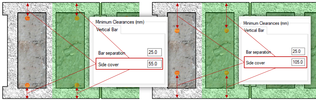
By default for designs with one bar per cell, vertical bars are placed in the middle of the wall. As soon as 2 bars are placed in each cell, they are positioned such that the cover distance between the outer edge of the bar and the outside face of the wall equals the “side cover” value in the “Minimum Clearances” section of the input window. By default, the side cover value is 55mm but this can be increased to move the reinforcement further from the face of the wall. The “Bar separation” value (by default, equal to 25mm) is checked against after the steel is placed based on the specified side cover. If the bars are too close together, such that the distance between the inside faces of each bar is less than the specified bar separation, the design will be unsuccessful.
If the symmetric option is disabled above the vertical steel section of the input window, rather than place both bars according to side cover, the first bar is placed based on side cover with the second then positioned using the bar separation input field. MASS will then check to ensure that the specified side cover is also satisfies between the second bar and the other side of the wall. Note that MASS will automatically place the steel closer to the tension face of the wall where it is most beneficial as long as the wall is subjected to loading that results in single curvature deflection for all load cases.
Fully grouting the wall, making changes to the masonry unit, and adjusting the steel positioning is the closest a MASS wall design can come to resembling that of a pilaster.
Applying Loads to a Pilaster Modeled in MASS
Once the cross section of a pilaster has been modeled within MASS, loading is the only remaining consideration needed before the software can produce helpful design results. Without making any changes to the way loads would be applied to a conventional wall design, the results created by the software are completely invalid (and likely massively under designed for the loads it will be resisting)! Starting with a quick primer on how MASS loads out-of-plane walls, this article will outline how a load can be changed to factor in the changes made to accommodate pilaster design.
Refresher on MASS Wall Loads
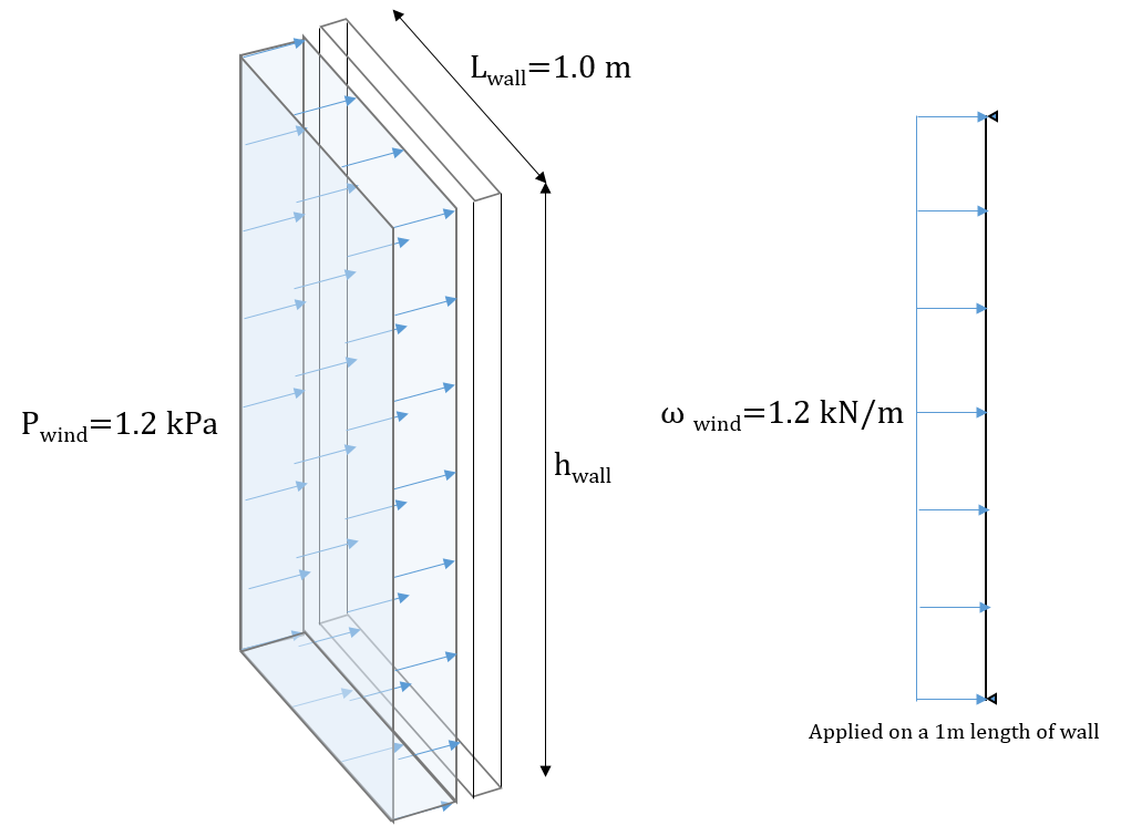
It is a common misconception that lateral, distributed loads are applied to wall modules in the form of pressures, rather than line loads. This mistake is often made without consequence because MASS designs walls on a per m basis so when a pressure applied in kPa or kN/m2 is divided by a one metre length, the result is a line load with the same magnitude as the initial pressure. For example, an unfactored wind pressure of 1.2kPa is applied in MASS as a line load of 1.2kN/m (per m of wall).
If the wall length were not exactly one metre, there would be a difference in magnitude between the applied wind pressure and the equivalent line load applied to the wall in MASS. For example, if looking at a 0.4m long pilaster, the same 1.2 kPa unfactored wind pressure would result in a line load of only 0.48 kN/m because the pilaster is resisting a much smaller tributary area of applied wind pressure.
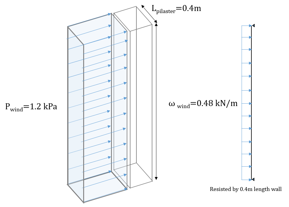
If the pilaster were still resisting all of the wind load applied to a one metre length then this magnitude would be the same, just like in the regular wall example, shown above the pilaster example.
When determining the loading on a pilaster section, it is likely that there is a much larger tributary area of load transferred from the walls on either side. This often results in large lateral line loads that the pilaster must be designed to resist. Consider an example where pilasters are spaced 3.2m apart along a wall with lateral and axial loads transferred to the pilaster section through the walls spanning between them. With each pilaster having a tributary width of 3.2m, the equivalent line load for a 1.2kPa unfactored wind pressure would be 3.84 kN/m applied along the height of the pilaster.
Even after accounting for tributary area, there is further adjustment needed in order for MASS to be useful for pilaster design.
Converting your Pilaster Loads for MASS
Recall the pilaster section as it is represented in MASS described earlier in this article. The unit thickness, face shell thickness, grouted area, and reinforcement positioning have been adjusted in order to model the section using MASS with the only remaining difference being the cross section length:
The length of the “wall” being designed is unable to be changed from 1m so all applied loads must be scaled up to take the additional cross section into account. Since the design in MASS is wider than the actual pilaster by factor of MASS design length to pilaster length, the loads must also be scaled by the same factor. This can be done using the expression below:

By multiplying each applied load by the ratio of MASS wall design length to the actual pilaster length, the loads are adequately scaled to ensure that the factored loading and resistances are adjusted equally. Consider the example below with a lateral, uniformly distributed load of 3.84kN/m and an axial load of 40kN applied from the roof level:
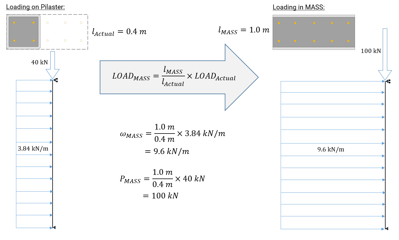
Since the section designed in MASS is 2.5 times the length of the actual pilaster being designed (1.0m/0.4m factor), the loads applied to the assemblage in MASS must also be scaled up by that same factor. This relationship holds true for all load types beyond line loads and axial loads.
Self-weight
While it is in many cases conservative to let the software include self-weight automatically, it is recommended to manually calculate and apply the magnitude of the self-weight force resting upon the critical section of the pilaster. The option to include self-weight can be disabled by un-checking the box at the bottom of the loads application window, shown below:
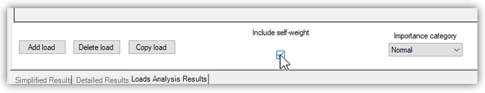
When applying the self-weight manually, be sure to apply it as a dead, axial load at the top of the wall. Ensure that in addition to taking into account the total area of masonry supported above the critical section, also make sure to scale this load up using the formula discussed in the previous section. While the MASS calculated value will be correct based on the modeled 1m long section, it does not include any other masonry not modeled within MASS and also makes some conservative assumptions that might be the topic of a future article. The help files can always be consulted for an explanation on how self-weight is calculated.
Design Example
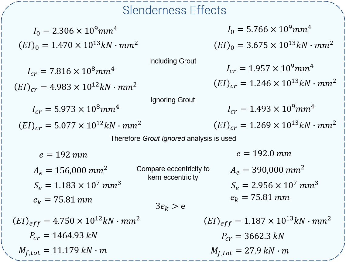
Looking at the elevation with 4m tall, 0.4m long pilasters spaced at 3.2m apart (referenced throughout this post), the results when calculated by hand can be compared to those of the MASS software to verify this approach. When the user has made the appropriate adjustments, the results produced by MASS can be valid for design purposes. The MASS file used to compare with hand calculations can be downloaded by clicking here. For simplicity, both the 40kN axial load and the 3.84kN/m line loads were applied as dead type loads so that there would be only one load combination, 1.4D. The exact pilaster unit created earlier was used for this exercise, having a 50mm thick face shell and the steel was placed such that layer 1 would be placed at d=290mm and layer 2 placed at d=100mm (achieved using a specified side over of 90.25mm). A summary can be seen below:
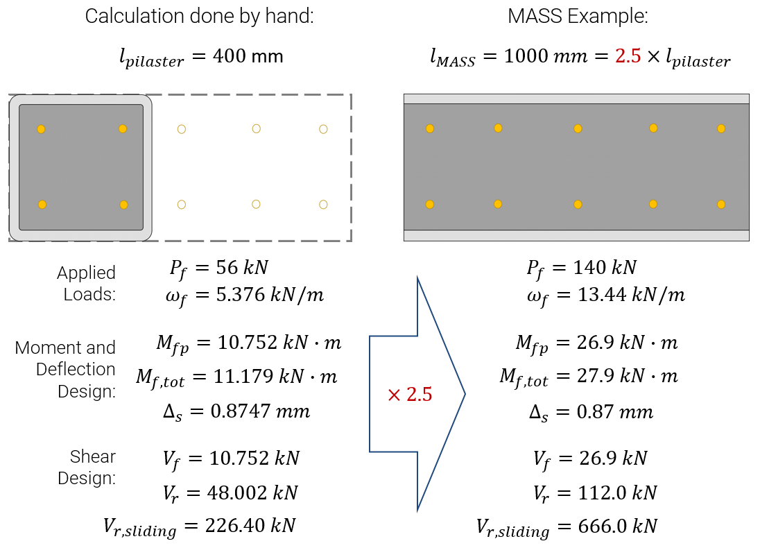
Note that nearly all of the values calculated by hand are directly proportional to their counterparts calculated using MASS. The only exceptions were measurements perpendicular to the length of the wall such as eccentricities, neutral axis locations, and deflections. While forces and moments all scaled proportionally, stress values such as vm were the same between hand and software calculations because they are independent of length.
Click to expand more a more detailed breakdown of these results
When determining the effective stiffness of the wall, it was checked both including and ignoring the effects of grout because the addition of grout cannot be used to reduce the effective stiffness. It was found that it was beneficial to ignore the grout when considering a cracked cross section which was then used to determine the overall effective stiffness taking both cracked and uncracked stiffness into account. This stiffness was then used to determine the critical buckling axial load which can be used to calculate the total factored moment. Since the section is relatively stiff and the applied axial load in this example is very low, the factored moment was only magnified by 3.5%.
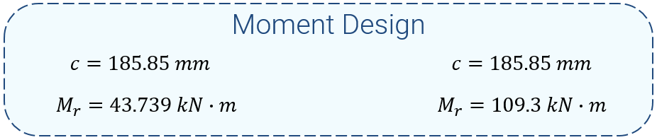
When designing the pilaster for bending moment, the neutral axis location was the same between hand calculations and the software. Due to the placement of reinforcement, one layer was found to be in compression (ignored) and the other layer did not yield (Fs=336.24MPa).
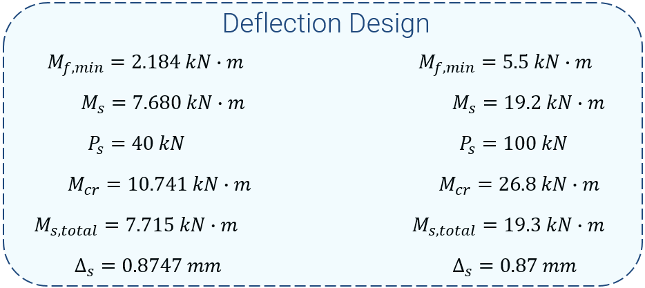
Since MASS only checks wind defection by default, the example file was modified for demonstration purposes. By changing the lateral force from a 9.6kN/m Dead line load to a 12.8kN/m Wind line load, the resulting service moment is equivalent (1.0D = 0.75W). Note that the Ms refers to the service moment without P-delta effects while Ms,total does include those effects. While the section in MASS is significantly stiffer than the hand calculation example, since the loads have also been scaled accordingly, the lateral deflections work out to being identical.
All of the values (with the exception of masonry shear strength, in MPa) scaled proportionally to section design length as well

If there are questions about the processes or approaches used to get any of these numbers please do not hesitate to contact CMDC.
Limitations of using MASS to help with pilaster design
While the process outlined in this article can serve as a useful guide for assisting with the design of a wall containing pilasters, there are some limitations which must also be acknowledged and accepted.
Composite action with the walls on either side is not considered
In particular to cases where the flush side of the wall is also the compression face, the building can be designed such that there is composite action where the vertical reinforcement within the pilaster is coupling in tension with the compression side of the walls on either side.
There is no way to model this within MASS so any pilasters designed with the assistance of this guide will depend solely on the capacity of the pilaster element itself. If composite action is required, it is best to perform this design by hand.
Any vertical bars in compression are ignored
As specified by the CSA Standards, reinforcement in compression cannot be included when evaluating the capacity of any masonry element without being adequately tied. There is no way to tie the steel in compression within a masonry wall constructed using conventional stretcher units so it is absent from all wall designs performed by the MASS software.
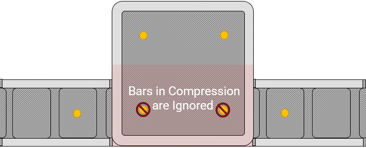
Since there is no way to convey to the software that the reinforcement is tied within the wall module, there is no way to consider steel in compression.
No more than two layers of tensile reinforcement can be placed
MASS only has the ability to place up to two bars per cell and as a result there is no way to take additional layers of reinforcement within a pilaster into account. Even when there are only two layers of reinforcement in tension, there is no way to place varying areas of steel within each layer.
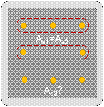
For example, if a pilaster were designed with reinforcement arranged in a three by three box formation, there is no way for MASS to place the area of three bars in the outermost layer and the area of two bars in the second layer. If a design requires more than two layers of tension reinforcement or a higher area of steel in the outermost layer, it is best to perform this design by hand.
…and one more thing to consider
As outlined in this post, there is considerable effort required to design a pilaster using MASS. While there are situations which warrant the use of pilasters, it may be worth considering the use of a conventional, rectangular wall constructed using a larger or stronger masonry unit. There is always the chance that it may be more economic to use a higher strength unit and resist the same loads without the need for pilaster units.
Summary
In general terms, this process can be summarized by saying that in order to model a pilaster using the wall module within MASS, the pilaster cross section can be scaled up to have a length of one metre. The loads must then be scaled upward by an equal amount to compensate for the increase in effective cross section. More specifically, the steps to accomplish this are outlines below:
The pilaster can be modeled with a longer cross section
Since the wall module in MASS only designs walls on a per metre basis, the pilaster must be modeled as having an increased length with all other properties specified accordingly.Click here to view more information on creating a pilaster section in MASS.
Fully grout the wall
Specifying that the wall be fully grouted in MASS ensures that no hollow masonry properties are applied within the design. Placing bars spaced every cell with the partially grouted selection also accomplished this. Click here to jump back to the grout section.
Modify the masonry unit
Using the Masonry Unit Database, the geometry of the unit can be adjusted to increase the overall thickness of the masonry unit as well as the thickness of each face shell. A step by step guide on how to do this can be found by clicking here and expanding the database instructions.
Position the reinforcement
By default, MASS only places one bar in the middle of each cell. The selections can be expanded to place up to 2 bars per cell and where they are places within the unit can be adjusted by modifying the values in the minimum clearances section of the input window. Click here to jump to the steel positioning section.
All applied loads must be scaled proportionally to reflect the increase in length
Since the pilaster has been modeled as a larger section, all loads must be applied in such a way as to account for this change. Click here to read the full section on load application.
Manually scale each load
Before any loads are applied within MASS, they must be scaled by the engineer to take the larger cross section into account. This is done by multiplying the magnitude of each load by the ratio of the length used by MASS to the length of the actual pilaster before applying them onto the wall in MASS. Click here for detailed instructions and an example to demonstrate how this can be done.
Manually calculate self-weight
While MASS can include self-weight automatically, there are limitations to how this is performed and which areas are taken into account. In particular to additional areas of masonry supported by the pilaster, it is best to manually calculate the self-weight before scaling the magnitude and applying to the wall within MASS. For more information, click here.
If you have any questions, please do not hesitate to call or email the Canada Masonry Design Centre.
The MASS software is a product of a joint partnership between CMDC and CCMPA. CMDC is the authorized provider for MASS Technical Support.